Table of Contents
Advertisement
Quick Links
Advertisement
Table of Contents

Subscribe to Our Youtube Channel
Related Manuals for Nady Systems U-800


Summary of Contents for Nady Systems U-800
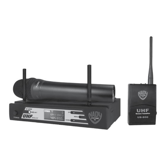
- Page 1 U-800 UHF 800-Channel Wireless System OWNER’S MANUAL...
-
Page 2: Table Of Contents
1. INTRODUCTION Thank you for choosing the Nady U-800 wireless system, and congratulations on your choice. The U-800 has the best performance and price value in professional UHF wireless, offering clear-channel, frequency-agile operation on the UHF band for interference-free performance in any application or locale. The U-800 delivers 800 user-selectable, frequency synthesized channels in the US frequency band 470MHz- 490MHz. -
Page 3: System Features
UH-800 HANDHELD MIC TRANSMITTER • Sleek metal housing with internal antenna for optimum aesthetics and durable long life • Features the Nady DM -10D unidirectional neodymium dynamic cartridge for optimum true sound, maximum feedback rejection and minimal handling noise • 800 easily selectable channels via IR Sync download for easy synchronization with receiver’s selected channel... -
Page 4: Quick User Controls Guide
4. QUICk USER CONTROLS GUIDE U-800 RECEIVER: FRONT VIEW 10 12 1. POWER BUTTON bUTTON push in to power receiver ON or OFF 2. POWER LED LED indicates receiver is turned ON 3. DUAL ANTENNAS permanently mounted., rotate to 45° as shown for optimal reception 4. - Page 5 A/b INDICATORS (9) will also be on, indicating channel transfer is complete. See also section “6. Selecting Group/Channel, IR Programming and Simultaneous Multichannel Operation” U-800 RECEIVER: BACK VIEW 19. UNBALANCED LINE OUT ¼” JACK Line level audio output, adjustable with volume control 20.
- Page 6 UH-800 HANDHELD TRANSMITTER: FRONT AND BOTTOM VIEW MIC BALL/ ANTENNA windscreen also functions as antenna, so for best operating range do not handle this antenna during use BATTERY COVER unscrew CCW to open battery tube to insert batteries AUDIO INPUT LEVEL normally set at middle position, turn knob with small flat head screw driver for optimum sound TWO AA BATTERIES operating from two AA batteries BATTERY COMPARTMENT holds two AA alkaline or NiMH batteries,...
- Page 7 UB-800 BODyPACK TRANSMITTER: FRONT VIEW 38. ANTENNA Removable antenna—should be attached during operation 39. INPUT JACK Locking 3.5mm mini-jack for connecting audio input cord from lapel mic (LT), Headmic™ (LT/HM), or instrument (GT) cable 40. AUDIO MUTE slide the switch to ON or OFF to mute audio with transmitter powered on 41.
-
Page 8: System Operation
The power LED and the backlight on the LCD will be off indicating the receiver is off. At power-off the U-800 receiver will store the last set- tings entered and re-display them at power-on. It can be reprogrammed to any new Group/Channel, or Mute level. -
Page 9: Powering The Receiver
DISPLAY (5) will now light and the receiver is operational. Adjusting Antennas The U-800 has two permanently attached, flexible elbow ANTENNAS (3) for diver- sity reception. Unfold and rotate these antennas to operate the receiver. The optimal positions of the antennas are flared 45° out from the receiver sides and 90° from each other. -
Page 10: Audio Level And Peak Led Indicator
Audio Level and Peak LED Indicator SYSTEM OpERATION The U-800 receiver has a 5 bar AF LCD (7) display that typically shows a few bars indicating normal level audio signal from the transmitter. Occasional flickering of the fifth AF LCD (peak level) on loud inputs to the transmitter is normal. If the AF LCD lights up full bars continuously decrease the input audio level to the transmitter or overload distortion may result. - Page 11 The microphone is now ready to use. The diversity A/B INDICATORS (9) on the U-800 receiver should now be on, indicating a received signal from the transmitter. When ready to speak, slide the AUDIO MUTE (36) to the ON position. The MUTE ICON (6) on receiver should be off.
- Page 12 Note: : The windscreen of the UH-800 functions as a built-in antenna. For proper operation, never remove the windscreen during use, or exchange with another type. For optimum range maintain line-of-sight between the transmitter and the receiver whenever possible. Holding the microphone tightly, bridging across the windscreen and Mic tube, will also lessen range.
- Page 13 The microphone is now ready to use. The diversity A or B INDICATORS (9) on the U-800 receiver should now be lit, indicating a received signal from the transmitter. When ready to speak, slide the AUDIO MUTE ON/OFF SWITCH (40) to the ON position.
-
Page 14: Selecting Group/Channel, Ir Programming And Simultaneous Multichannel Operation
Connecting Input Audio Source Lapel/Head Mic Uses (UB-800 LT/HM) The mini 3.5mm locking INPUT JACK (39) is for connecting the audio input from a lavaliere/lapel Mic (LT), a Head Mic™ (HM), or an instrument (GT) cable, depending on which transmitter version is being used. Secure the connection to the cable by tight- ening the cable mini plug’s outer ring counterclockwise. - Page 15 This facilitates easy setup by enabling quick selection of stored channels for any group, i.e, selecting any group will automatically display the last channel selected for that group. See section “11. U-800 Frequency Lists” for available channels in each group. The previous group and channel used is stored in memory automatically when receiver and transmitter are turned off after operation.
- Page 16 Instructions for Setup of Simultaneous Multichannel Operation This U-800 receiver is capable of finding an open channel with its autoscan capabil- ity. This built-in feature is a quick, convenient way to set up many wireless systems at the same location for simultaneous multichannel operation.
-
Page 17: Cautions And Troubleshooting
Adjusting the Mute Level / RFSquelch. If receiving interference on a selected channel with the transmitter off, or if you en- counter interferences in operating multiple U-800 systems simultaneously at the same location see: “6. Selecting Group/Channel, IR Programming and Simul- taneous Multichannel Operation”... -
Page 18: Miscellaneous Tips
8. MISCELLANEOUS TIpS • The receiver antennas should be kept away from any metal surfaces whenever possible as they can reflect away or shield the incoming RF signal. • If the receiver’s volume control is set too high, it may overdrive the input of the attached audio mixer, causing distortion. -
Page 19: Specifications
9. SpECIFICATIONS U-800 OVERALL SYSTEM PERFORMANCE Operating Frequency Range 470MHz–510MHz, two bands Freq. Synthesized (800 channels switchable) 25kHz/step pLL system frequency stability <0.005% Frequency Response 50Hz-18kHz +/-3db Dynamic Range 120db Harmonic Distortion <0.5% Modulation FM (F3E) +/-50kHz normal, +/-100kHz max... -
Page 20: Frequency Plan
UB-800 BODYPACK TRANSMITTER RF Output Power +17dBm Max, +14dBm (25mW typical) Harmonic/Spurious Emission -50dbc normal Input Impedance 4.7k Ω (Lavalier); 500 k Ω (Instrument) Controls power and Audio ON/OFF switches, Input Level Input Connector Locking 3.5mm mini-jack LED Display bi-Color - power ON (GREEN) and Low battery ON (RED) Antenna Type External Removable... -
Page 21: Frequency Lists
CH 798 489.925 CH 13 488.325 CH 799 489.950 CH 14 489.425 CH 800 489.975 Band 1: U-800 Frequency Listing Channels for each Group from 1B to 1F (470.000MHz-489.975MHz) USER SELECTABLE CHANNELS 470.000 471.250 472.500 473.750 475.000 476.250 477.500 478.750 480.000... -
Page 22: Optional Accessories
If your unit is out of warranty, please enclose a cashier’s check or money order (or pay by credit card) per instructions by the Nady Service Department. Ship your unit prepaid to: Nady Systems, Service Dept, 6701 Shellmound Street, Emeryville, CA 94608. -
Page 23: One Year Limited Warranty
2) Send the unit back to Nady Systems, 6701 Shellmound Street, Emeryville, CA, 94608, freight pre-paid. You must include proof of date and place of purchase (i.e., photocopy of your bill of sale) or Nady cannot be responsible for repair or replacement. Nady Systems, Inc. will not repair, nor be held responsible, for any units returned without proper identification, return address, and RA number clearly marked on the package. - Page 24 Nady Wireless Systems are type accepted under FCC rules parts 90, 74 and 15. The device complies with RSS-210 of Industry & Science Canada. Operation is subject to the following two conditions: (1) this device may not cause harmful interference and (2) this device must accept any interference received, including interference that may cause undesired operation.
Need help?
Do you have a question about the U-800 and is the answer not in the manual?
Questions and answers