
Subscribe to Our Youtube Channel
Related Manuals for Oxford Instruments ANDOR TuCam


Summary of Contents for Oxford Instruments ANDOR TuCam
- Page 1 TuCam Version 1.2 revised 01 June 2015 User Guide andor.com © Andor Technology 2015...
-
Page 2: Table Of Contents
TuCam TABLE OF CONTENTS SECTION 1: INTRODUCTION ............5 ....................6 echnical upporT ......................7 pecificaTionS 1.2.1 M ................. 8 echanical iMenSionS ..................... 9 ranSMiSSion urveS ..................10 erieS rincipleS ................11 orking WiTh The SerS uiDe ......................11 iSclaiMer &... - Page 3 TuCam SECTION 3: MAINTENANCE ............32 ) ..................... 32 leaning xTernal SECTION 4: TROUBLESHOOTING ..........33 ..............33 Mage noT parcenTric WiTh MicroScope ..............33 Mage noT parfocal WiTh MicroScope ................. 33 uniforM iMage inTenSiTy ................33 aMera iMageS ouT of alignMenT ..................
-
Page 4: Revision History
TuCam evision istoRy Version Released Description 03 Oct 2012 Initial Release 03 Oct 2014 Added weights information (Section 1.2.1) Updated company patent statement and note re access to new editions of the user guide (Section 1.7) Updated Accessories listing (Section 1.9) Translated content into new functional template, updated presentation and branding (All Sections) Updated product Images to current appearance. -
Page 5: Section 1: Introduction
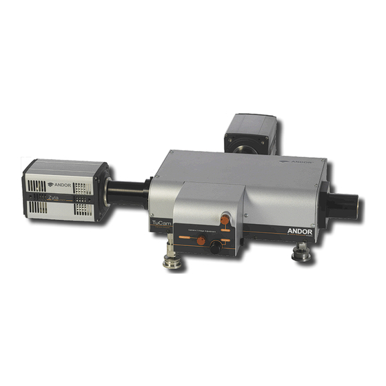
TuCam SECTION 1: INTRODUCTION Firstly thank you for choosing Andor’s TuCam dual camera adapter. We are delighted you have selected our equipment to fulfill your requirements. Figure 1: Tucam configured for C-mount. Here are some of the feature and benefits available to you: •... -
Page 6: T Echnical S Upport
TuCam 1.1 t ecHnical uppoRt If you have any questions regarding the use of this equipment, please contact the representative* from whom your system was purchased, or: Europe Andor Technology Andor Technology 7 Millennium Way 425 Sullivan Avenue Springvale Business Park Suite # 3 Belfast South Windsor... -
Page 7: S Pecifications
TuCam 1.2 s pecifications NOTE: The specifications quoted below are for the 1.2x CSU version: PARAMETER SPECIFICATION General Optimized for CSU-X Focal plane size 1.2x (W x H) 12 x 8.4 mm Uniformity > 90 % Wavelength range 400 - 750 nm Typical throughput 94 % Distortion... -
Page 8: M Echanical D Imensions
TuCam 1.2.1 M ecHanical iMensions Weights for C-Mount Version: Cassette = 0.35 Kg [12 oz] Main unit = 4.6 Kg [10 lb 2 oz] Figure 2: C-Mount Version 396.4 [15.61] Weights for CSU-X Version: 277.4 [10.92] Cassette = 0.35 Kg [12 oz] Main unit = 5.5 Kg [12 lb 2 oz] Figure 3: CSU-X Version Version 1.2 rev 01 June 2015... -
Page 9: Ransmission Urves
TuCam 1.3 t RansMission uRves CSUX version CSUX version Wavelength (nm) Figure 4: Transmission curve for CSU-X version C-mount version Wavelength (nm) Figure 5: Transmission curve for C-mount version Version 1.2 rev 01 June 2015... -
Page 10: T U C Am S Eries P Rinciples
TuCam 1.4 t eRies Rinciples The TuCam is based around our own unique design to afford the user a diversity of options. The TuCam is pre-aligned and optimized at our factory prior to shipping, so the user will only ever need to adjust the focus and minor adjustments to the cassette. -
Page 11: W Orking With The U Sers G Uide
Andor and the Andor logo are trademarks of Andor Technology. Andor Technology is an Oxford Instruments Company. All other marks are property of their owners. Changes are periodically made to the product and these will be incorporated into new editions of the manual. New releases of the manual are available through MyAndor: http://my.andor.com/login.aspx. -
Page 12: A Ccessories
TuCam 1.9 a ccessoRies A wide range of accessories are available to configure your TuCam as shown in the tables below: Table 1: Standard filter sets ANDOR PART NUMBER SHORT DESCRIPTION LONG DESCRIPTION TR-EMFS-F01 GFP/RFP Dichroic Filter set Semrock FF01-514/30-25, FF02-617/73, Dichroic FF580-FDi01-25x36 TR-EMFS-F02 CFP/YFP Dichroic Filter set Semrock FF01-475/28, FF01-550/49-25, Dichroic FF509-FDi01-25x36... -
Page 13: Section 2: Installation
TuCam SECTION 2: INSTALLATION 2.1 u npacking Before unpacking the instrument, allow the shipping box to fully acclimatize to room temperature. Whilst the TuCam requires no special placement in a controlled environment, it should be noted that it is a precision instrument that will perform best when set up and operated properly. -
Page 14: I Nstalling S Upport L Egs
TuCam 2.2 i nstalling uppoRt The Tucam base unit will have been supplied with three height adjustable support legs. Two support legs are attached to the TuCam at the camera end and one at the front. The legs simply screw into the base unit in the locations shown below. The leg height is adjusted by rotating the knurled ring at the base;... -
Page 15: M Icroscope & Csu M Ounting A Ccessories
TuCam 2.3 M & csu M icRoscope ounting ccessoRies A number of accessories are available for raising the optical axis height of a range of microscopes and the CSU unit (see Section 1.9). The individual microscope mounts are designed to raise the optical axis of the LHS port to 110 mm to provide a consistent height for attaching other accessory units. -
Page 16: C Assette F Ilter I Nstallation
TuCam 2.4 c assette ilteR nstallation NOTE: For the best performance it is recommended that you have the filter set installed at our factory at the time of purchase. TuCam units are tested with each individual filter cassette prior to ship and we therefore cannot guarantee our specifications if filter sets are installed by the customer. - Page 17 TuCam To install the dichroic mirror, carefully remove screws 1 and 2 that hold on the block for the Camera 2 emission filter (see photograph below). Remove the block and set it to the side. Next, remove screws 3 and 4 and the ‘C’-shaped block that holds the dichroic mirror in position.
-
Page 18: M Ounting And R Emoving The C Assette
TuCam 2.5 M ounting anD eMoving tHe assette The filter cassette(s) supplied with your system have been pre-aligned prior to shipping. To install the cassette firstly remove the bypass stop screw and then slide the cassette onto the dovetail rail. Replace the bypass stop screw as it acts as a mechanical stop for the cassette in the bypass position. -
Page 19: C Onnecting A T U C Am To A M Icroscope I Maging P Ort
TuCam 2.6 c onnecting a aM to a icRoscope Maging Microscope Cameras TuCam Optical axis Figure 14: Example C-mount setup showing optical axis The c-mount version of the TuCam has been designed to be attached to one of the imaging ports of a microscope. The main microscope manufacturers are supported: namely Olympus, Nikon, Zeiss and Leica. - Page 20 TuCam Attach the microscope c-mount adapter to the entrance port of the TuCam and then to the port on the microscope body ensuring that it is securely tightened. Using a spirit level, adjust the height of the rear support legs until the TuCam unit is level.
- Page 21 TuCam The position of the TuCam can be altered to centre the optical axis of the scope on the collection lens. To do this, firstly place the alignment pinhole in the imaging path of camera 1. Set the scope to illuminate through the port that the TuCam is attached to using the microscopes lamp source.
- Page 22 TuCam Remove the alignment pinhole and place it in the Camera 2 path. Slide the cassette onto the dovetail and lock in position. Observe the bright spot on the alignment pinhole and use the vertical and horizontal adjustment controls on the front porch to centre the spot on the pinhole to centre the spot on the pinhole.
- Page 23 TuCam The appropriate c-mount adapter should be attached to the camera that is to be used on the particular imaging path. The length of the adapter is magnification dependent (shorter lengths are for lower magnification). The adapters and cameras should then be slid into the camera mounts on the TuCam unit and locked in position. A spirit level should be used to ensure the cameras are level.
-
Page 24: A Ligning The T U C Am Using I Q
TuCam 2.7 a ligning tHe aM using i The following section indicates how to align the TuCam using Andor iQ. Other image overlay software is available and you should follow the same procedure to achieve similar results. Connect the power supplies to the cameras and USB/Controller card Link cables to the PC and cameras. Power up the cameras and start iQ with a configuration that contains the 2 cameras as a minimum. - Page 25 TuCam Figure 23: Alignment target for CSU version Once focused, snap the image and save it as Camera1 Grid. At this point you should make sure not to move the microscope stage or adjust focus as you will end up aligning camera 2 to an image that is no longer there. Switch to Camera 2 in the Acquisition/Auxiliary Devices window.
- Page 26 TuCam On the first window of the Wizard select Use Reference Image and click Next >> Figure 25: Camera Alignment Window This will bring up the image list, e.g.: Figure 26: Image List Choose the image that had been taken previously using Camera 1 and click Select to advance to the next window. Version 1.2 rev 01 June 2015...
- Page 27 TuCam Figure 27: Selection of Camera Alignment options On this window tick on the Show Difference, Normalize Images and Automap checkboxes. An overlay of the two imaging paths will now be visible with the image from Camera 2 running live. Use the x and y adjustment screws on the cassette to approximately align the image from Camera 2 with that from Camera 1.
- Page 28 TuCam Sometimes you may find that there is a slight difference in the magnification of the two imaging paths. This is caused by the two imaging paths not being accurately focussed and can easily be corrected for by adjusting the focus of the imaging path for camera 2.
- Page 29 TuCam On Camera1 set the camera acquisition parameters so as to obtain an image similar to that above, making sure that none of the pixels are saturating. The pinholes also allow a highly accurate focus to be obtained. In the iQ software select the Region Histogram from the Analysis menu.
- Page 30 TuCam Click on the checkboxes as before and correct any angular misalignment by rotating Camera 2. Use the x and y adjusters to obtain the best alignment of the image by minimizing the Max Diff score. Take care not to move too far away from your current position as it is easy to get lost due to the lack of a reference point.
-
Page 31: C Onnecting A T U C Am To The Csu
TuCam 2.8 c onnecting a aM to tHe The TuCam has been designed to integrate with the CSU and Sutter filter wheels. For best results it is recommended that the system be mounted on a level optical table or breadboard and that the microscope, CSU and filter wheel are level and aligned on the optical axis of the microscope port. -
Page 32: Section 3: Maintenance
TuCam SECTION 3: MAINTENANCE There are no user serviceable parts inside the unit. If the equipment is used in a manner not stated by Andor, the warranty may be impaired. 3.1 c leaning xteRnal Only use a dry, clean, lint free cloth to clean all external painted surfaces. If necessary, use a water diluted detergent to lightly dampen the cloth - do not use Isopropyl alcohol, solvents or aerosols. -
Page 33: Section 4: Troubleshooting
TuCam SECTION 4: TROUBLESHOOTING 4.1 i Mage not paRcentRic WitH MicRoscope TuCam unit is not properly aligned with optical axis of microscope. Slide the TuCam laterally on the table and adjust the support leg heights until the image obtained in Camera 1 is parcentric with the image in the microscope eyepiece. Once you are satisfied that the image on Camera 1 is parcentric securely fasten the TuCam unit onto the optical table. -
Page 34: M Agnification Difference
TuCam 4.5 M agnification DiffeRence Slight differences in the magnification of the 2 imaging paths can occur due to the manufacturing tolerances in the lens focal lengths and if the two images are not accurately focused. Small differences may be corrected by slightly adjusting the focus of camera 2. -
Page 35: Section 5: Other Information
TuCam SECTION 5: OTHER INFORMATION erms and ondiTions of ale and arranTy nformaTion The terms and conditions of sale, including warranty conditions, will have been made available during the ordering process. The current version may be viewed at: http://www.andor.com/pdfs/literature/Andor_Standard_Warranty.pdf 2006 (Weee) asTe leCTroniC and leCTriCal...
Need help?
Do you have a question about the ANDOR TuCam and is the answer not in the manual?
Questions and answers