
Subscribe to Our Youtube Channel
Related Manuals for Oxford Instruments Andor Balor


Summary of Contents for Oxford Instruments Andor Balor
- Page 1 Balor Version 1.0 rev 14 Aug 2019 Hardware Guide andor.com © Andor Technology Ltd. 2019.
-
Page 2: Table Of Contents
Balor TABLE OF CONTENTS SECTION 1: INTRODUCTION ..................11 TECHNICAL SUPPORT ......................12 DISCLAIMER .......................... 13 COPYRIGHT AND PROTECTIVE NOTICES ................13 TRADEMARKS AND PATENT INFORMATION ............... 13 SUPPLIED COMPONENTS ....................14 1.5.1 ....................15 alor odel ptions 1.5.2 ....................15 ptional ccessories SECTION 2: PRODUCT OVERVIEW ................ - Page 3 Balor 3.6.2 ................... 23 ooling onnectors COOLANT RECOMMENDATIONS ..................24 CONNECTING THE LIQUID COOLING SYSTEM ..............24 3.8.1 ................... 24 onnecting the oolant oses 3.8.2 ................24 isconnecting the oolant oses INSTALLING SOFTWARE ....................... 25 3.9.1 ................. 25 iniMuM oMputer equireMents 3.9.2 cXp d...
- Page 4 Balor 4.5.5 ......32 verview of the olling hutter and loBal hutter echanisMs UNDERSTANDING READ NOISE IN SCMOS ................ 33 4.6.1 ....................34 purious oise ilter 4.6.2 ................... 34 leMish orrection ilter 4.6.3 ..................35 ulti aMplifier dynaMic range SENSOR READOUT OPTIMIZATION ..................35 4.7.1 (aoi ) .......................
- Page 5 Balor 4.10.8 g - 100% d ......55 loBal hutter ycle Xternal Xposure riggering 4.10.9 e ................... 56 Xternal tart riggering 4.10.10 g ..............57 loBal hutter riggering onstraints 4.11 ACQUISITION MODES ......................58 4.11.1 s ......................... 58 ingle 4.11.2 K ......................
- Page 6 Balor APPENDIX A: TECHNICAL SPECIFICATIONS ............66 APPENDIX B: MECHANICAL DRAWINGS ..............69 APPENDIX C: DEWPOINT INFORMATION ..............70 APPENDIX D: REFERENCE INFORMATION ............... 71 APPENDIX E: OTHER INFORMATION ................ 72 Version 1.0 rev 14 Aug 2019...
- Page 7 Balor evision istoRy Version Released Description 14 Aug 2019 Initial release. pdates to tHe anUal Changes are periodically made to the product and these will be incorporated into new editions of the manual. Please check for new releases of the manual in MyAndor: http://my.andor.com/login.aspx. If you find an issue in this manual please contact your customer support respresentative (Section 1.1) with a description of the issue.
- Page 8 Balor afety and aRning nfoRMation READ THIS INFORMATION FIRST If the equipment is used in a manner not specified by Andor, the protection provided by the equipment may be impaired. Before using the system, please follow and adhere to all warnings, safety, manual handling and operating instructions located either on the product or in this Hardware Guide.
- Page 9 Balor 20. If any ingress of liquids has occurred or is suspected, unplug the mains cables, do not use, and contact Andor Customer Support. 21. Liquid Cooled Only models must be connected to a water/liquid cooling system that is switched on before the camera.
- Page 10 Balor aRning and afety abels The serial label of the Balor camera (below) is located on the back of the camera. It shows the product model, serial number and the build date. Model No.: BLR-F401-NN Serial No.: BSC - 123456 Date: July 01, 2019 npacking...
-
Page 11: Section 1: Introduction
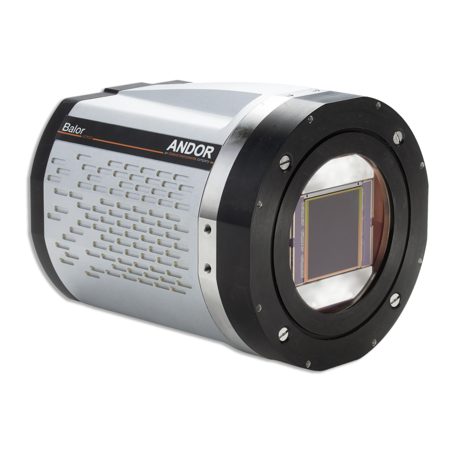
Balor SECTION 1: INTRODUCTION This manual provides an overview of the Balor camera series. Balor houses a large area high resolution 16.9 Megapixel sCMOS sensor and has cooling configurations to suit demanding applications such as Astrophysics and Astronomy or X-ray/Neutron radiography. This manual includes a description of the main features of Balor, its installation, routine operation and troubleshooting. -
Page 12: Technical Support
Balor 1.1 t ecHnical UppoRt If you have any questions regarding the use of this equipment, please contact the representative* from whom your system was purchased, or: Europe Andor Technology Ltd. Andor Technology 7 Millennium Way 300 Baker Avenue Springvale Business Park Suite # 150 Belfast Concord... -
Page 13: Disclaimer
RadeMaRks and atent nfoRMation Andor and the Andor logo are trademarks of Andor Technology Ltd. Andor Technology Ltd. is an Oxford Instruments company. All other marks are property of their owners. Balor Manufacturers Information Andor Technology Ltd., Belfast, BT12 7AL, UK. -
Page 14: Supplied Components
Balor 1.5 s Upplied oMponents Description Quantity Balor sCMOS Camera (model as ordered: refer to Section 1.5.1 Supplied with shipping plate fitted) Software & Driver Hardware Guide in CDs or Flash Drive electronic format (Solis is ordered separately) Power Supply Power Cord 1 x 15 V (Camera) (Country specific) -
Page 15: Alor Odel Ptions
Balor 1.5.1 b aloR odel ptions There are a number of models of Balor 17F-12 camera, based on the sensor variant and cooling performance (see also Section 2.1). The options for each model can be identified by the code suffixes added to the BLR- product code as outlined below: Sensor Front illuminated sCMOS, 16.9 MP (4128[W] x 4104[H]) 12 mm pixels... -
Page 16: Section 2: Product Overview
Balor SECTION 2: PRODUCT OVERVIEW This section provides an overview of the Balor. Please note that Balor configuration including housing, cooling connectivity and mounting flange may vary for your specific model. Please refer to the additional information supplied for details of any model specific differences. 2.1 e xteRnal eatURes of tHe... -
Page 17: Rear Panel
Balor 2.2 R anel TTL/Logic Liquid Cooling OFF/ON Switch Camera Power Input IRIG-B Camera Cooler Power Input CoaXPress Figure 3: Rear panel. CoaXPress 4 lane CoaXPress cable enables high speed connection to the control PC (@ 6.25 Gbps) at up to 25 m distances. TTL / Logic The TTL/Logic connection permit connection to other devices for synchronisation and control of fire, trigger and shutter operations. - Page 18 Balor • AUX_OUT_1 supplies the ‘FIRE ALL’ output by default. This is the logical AND of the FIRE pulses associated with Row #1 and Row #n (the last row read out in the image frame). Therefore the FIRE ALL pulse represents the time within a frame when all rows on the sensor are simultaneously exposing.
-
Page 19: Power Requirements
Balor 2.3 p oWeR eqUiReMents Ensure that the power connectors for the camera are inserted securely. The connectors are keyed to aid correct orientation. A 15 V DC External Power Supply supplies the camera electronics and a 24V DC External Power Supply supplies the Thermo-Electric Cooler. -
Page 20: Section 3: Installation
Balor SECTION 3: INSTALLATION WARNINGS: • PRIOR TO COMMENCING INSTALLATION, THE USER SHOULD REFER TO THE SAFETY AND WARNING INFORMATION AND UNPACKING INSTRUCTIONS AT THE BEGINNING OF THIS MANUAL. • THE BALOR WEIGHS ~9 KGS (~17.6 LBS). DUE CARE MUST BE TAKEN WHEN LIFTING THE CAMERA. ENSURE THAT THE MOUNTING AND CONNECTED ASSEMBLY IS SECURE AND ABLE TO SUPPORT THE WEIGHT OF THE CAMERA. -
Page 21: Attaching To Mounting Posts
Balor 3.3 a ttacHing to oUnting osts Four sets of 2x ¼ -20 UNC mounting holes are located at each 90 degrees. For further information, refer to the mechanical drawings in Appendix B. 3.4 c onnecting tHe aloR aMeRa to tHe The Balor connects to a PC via CoaXPress (4 Lane CXP-6)- this enables a high speed connection over distances of up to 25 metres. -
Page 22: C Onnecting The C Amera To The Cxp (Pci E ) C Ard
Balor 3.4.2 c cxp (pci onnecting tHe aMeRa to tHe • Connect the 4 Lane CXP-6 cable from the camera to the CXP (PCIe) card on the control PC. Note that the order of the CXP cables is not important- these are automatically configured by the camera and control card. -
Page 23: Connecting A Cooling System
Balor 3.6 c onnecting a ooling ysteM The Balor camera is available as a Liquid Cooled Only or “Flexi” models. The Liquid Cooled Only model uses liquid cooling only so must be connected to an operational cooling system before it is switched on. This model provides the maximum cooling and lowest noise. -
Page 24: Coolant Recommendations
Balor 3.7 c oolant ecoMMendations • Coolant temperature: Refer to the temperatures specified in Technical Specifications. Note that cooling performance may be affected by distance between camera head and cooler. • Recommended coolant: water or water/glycol mix depending on the ambient environmental temperature during operation. De-ionized water (without additives) may be used as the coolant. -
Page 25: Installing Software
Balor 3.9 i nstalling oftWaRe 3.9.1 M iniMUM oMpUteR eqUiReMents • 3.0 GHz quad core processor or equivalent • 16 GB RAM • Hard drive: 3 GB/sec write speed recommended for the data rate associated with the max. frame rates. 200 MB free hard disc to install software x8 PCIe 2.0 slot. -
Page 26: Hecking Setting Bios Options For Pc S Not Supplied By
Balor 3.9.5 c & Hecking setting bios options s not sUpplied by ndoR Enter the BIOS menu when starting PC. For Dell workstations, press F12 at start-up and select System Setup in the One Time Boot Menu. For Dell workstations 3 options in the Performance menu of the BIOS need to be checked/set: •... -
Page 27: Using The Balor Camera
Balor 4.4 U sing tHe aloR aMeRa Once set-up the Balor camera is controlled through the camera control software. Please refer to the information supplied with the camera control software (available separately) for further details e.g. Andor Solis or SDK3. For information on the features available with the Balor please refer to the remainder of Section 4. -
Page 28: Xtended Ynamic Ange (Edr)
Balor 4.4.2 e (edR) xtended ynaMic ange Balor provides an exceptional dynamic range on account of the combination of low noise floor and high signal handling provided by the large well depth capacity. Dynamic Range = well depth/noise floor A multi amplifier architecture is utilised to enable both low noise, and maximum well depth to be used simultaneously. This delivers a very high linearity of >99.7% across this range allowing for quantitative analysis. -
Page 29: R Olling S Hutter
Balor 4.5.1 R olling HUtteR The Balor can function in what is termed Rolling Shutter operation. This describes the sequence in which successive rows of pixels are read from the sensor array in a “rolling wave” effect. In Rolling Shutter, adjacent rows of the array are exposed at slightly different times as the reset and readout waves sweep through the sensor. -
Page 30: G Lobal S Hutter
Balor 4.5.2 g lobal HUtteR Global Shutter mode, which can also be thought of as a ‘snapshot’ exposure mode, means that all pixels of the array are exposed simultaneously. In most respects, Global Shutter can be thought of as behaving like an Interline CCD sensor. Before the exposure begins, all pixels in the array will be held in a ‘keep clean state’, during which charge is drained into the anti-bloom structure of each pixel. -
Page 31: Electing Olling Hutter Or Lobal Hutter
Balor 4.5.3 s electing olling HUtteR oR lobal HUtteR The selection of Rolling Shutter or Global Shutter modes depends on your specific experimental conditions. A summary of the key parameters for each mode is shown in Table 1: Table 1: Key parameters of Rolling and Global Shutter modes. Parameter Rolling Shutter Mode Global Shutter Mode... -
Page 32: O Verview Of The R Olling S Hutter And G Lobal S Hutter M Echanisms
Balor 4.5.5 o veRvieW of tHe olling HUtteR and lobal HUtteR ecHanisMs In Rolling Shutter mode, charge transfer happens on a per row basis whilst in Global Shutter charge transfer happens for the whole sensor or globally. To read out a pixel in Rolling Shutter mode, the following occurs within the analog circuitry: 1. -
Page 33: Understanding Read Noise In Scmos
Balor 4.6 U cMos ndeRstanding oise in s sCMOS technology boasts an ultra-low read noise floor that significantly exceeds that of even the best CCDs, at such high pixel readout speeds. For those more accustomed to dealing with CCDs, it is useful to gain an understanding of the nature of read noise distribution in CMOS imaging sensors. -
Page 34: S Purious N Oise F Ilter
Balor 4.6.1 s pURioUs oise ilteR The Spurious Noise filter corrects for pixels that would otherwise appear as spurious ‘salt and pepper’ noise spikes in the image. The appearance of such noisy pixels is analogous to the situation of Clock Induced Charge (CIC) noise spikes in EMCCD cameras, in that the overall noise of the sensor has been reduced to such a low level, that the remaining small percentage of spurious, high noise pixels can become an aesthetic issue. -
Page 35: M Ulti Amplifier Dynamic Range
Balor 4.6.3 M Ulti aMplifieR dynaMic Range The multi-amplifier architecture of the sCMOS sensor in Balor eliminates the need to choose between low noise or high capacity, and the signal can be sampled simultaneously by all amplifiers. As such, the lowest noise of the sensor can be harnessed alongside the maximum well depth, affording the widest possible dynamic range. -
Page 36: U Sing Roi S (Aoi S )
Balor 4.7.1 U (aoi sing Region of Interest (ROI) also called Area of Interest (AOI) can be selected so that only a defined region of the sensor is used. This smaller “cropped” region of the sensor can subsequently be read out much faster than the full sensor area so that frame rates may be significantly higher (see the preceding table). -
Page 37: Rolling Shutter
Balor 4.9 R olling HUtteR 4.9.1 R olling HUtteR ecHanisM The basic mechanism of Rolling shutter has previous been described, see section 4.5.5, this section looks in more detail at the read out under differing acquisition settings, for example exposure length, cycle time and triggering scheme. It also describes timing differences between Rolling Shutter and Rolling Shutter - 100% Duty Cycle. -
Page 38: R Olling S Hutter S Ignals
Balor 4.9.2 R olling HUtteR ignals The Rolling Shutter signals in the diagrams are as follows: • EXT/SW: Represents an external TTL trigger supplied to the camera or a trigger command sent via software in response to a user action (e.g. a button press). •... -
Page 39: R Olling S Hutter I Nternal T Riggering
Balor 1 Row is the time taken to perform 616 (504 in Rolling Shutter - 100% Duty Cycle) clock cycles. The sensor read out is designed to digitise 4 rows simultaneously hence a Full Frame readout is 4104/4 rows x 616 clock cycles. “T ”... - Page 40 Balor Figure 12: Rolling Shutter Internal Triggering (Part 2: exposure time > readout time). Figure 13: Rolling Shutter Internal Triggering (Part 3: Row 1, of the second exposure starts before, Row N, of the first exposure completes). Table 5: Rolling Shutter Internal Triggering Timing Parameters. Parameter Minimum Maximum...
-
Page 41: R Olling S Hutter - 100% D Uty C Ycle I Nternal T Riggering
Balor 4.9.5 R - 100% d olling HUtteR ycle nteRnal RiggeRing Rolling Shutter - 100% Duty Cycle in Internal Trigger maximizes the acquisition duty cycle and the frame rate by removing the Reset phase from the acquisition sequence. In this mode, the action of reading out also starts the next acquisition and hence the cycle time is the same as the exposure time. -
Page 42: Xternal Oftware Riggering
Balor 4.9.6 e xteRnal oftWaRe RiggeRing In this section, both External and Software Trigger are described in the same diagram as the acquisition sequence is the same. The trigger event can either be from the EXT Trigger input or sent via software. While waiting on the trigger event, the sensor is put into a “pre-scan read out cycle”... - Page 43 Balor Figure 16: Rolling Shutter - External Triggering (Part 2: Second exposure starts before readout completes). Table 7: Rolling Shutter External/Software Triggering Timing Parameters. Parameter Minimum Maximum Exposure 1 Row 3600 s Maximum (Exposure + 5 Row, Cycle Time (1/Frame Rate) 1 Frame + 3 Row) EXT Trig Pulse Width 2 Sensor Speed Clock Cycles...
-
Page 44: R Olling S Hutter E Xternal E Xposure T Riggering
Balor 4.9.7 R olling HUtteR xteRnal xposURe RiggeRing While waiting on the trigger event, the sensor is put into a “pre-scan read out cycle” which performs a continuous Rolling Reset which ensures that charge build up on the sensor is kept to a minimum while waiting for the trigger event. The ARM signal is asserted to indicate it is ready to detect an incoming trigger input. -
Page 45: R Olling S Hutter - 100% D Uty C Ycle E Xternal E Xposure T Riggering
Balor 4.9.8 R - 100% d olling HUtteR ycle xteRnal xposURe RiggeRing In this mode, every positive edge of the external trigger will initiate a frame read out and start a new exposure. The period of external trigger pulse defines exposure and cycle time for each frame read out. On detection of the first positive edge, a frame read out is initiated, this frame is discarded as it does not contain the correct exposure period. -
Page 46: R Olling S Hutter S Tart T Riggering
Balor 4.9.9 R olling HUtteR taRt RiggeRing In this mode the camera will wait for a single external trigger event. Once this external trigger event is detected, the camera will progress as if the camera was in internal trigger mode (see Section 4.10.4). The ARM signal indicates to the user when the camera is ready to detect an External Start Trigger. -
Page 47: Olling Hutter Riggering Onstraints
Balor 4.9.10 olling HUtteR RiggeRing onstRaints Table 10 below shows a summary of constraints when operating in Rolling Shutter mode: Table 10: Summary of Rolling Shutter constraints. Fast Trigger Rolling Shutter Triggering Modes Exposure Range Trigger Exposure Pulse Jitter Switching Width User settable exposure time Internal... -
Page 48: Global Shutter
Balor 4.10 g loBal hutter 4.10.1 lobal HUtteR ecHanisM Global Shutter can also be thought of as a ‘snapshot’ exposure mode, meaning that all pixels of the array are exposed simultaneously. Before the exposure begins, all pixels in the array are cleared of charge using the Global Clear. At the start of the exposure each pixel simultaneously begins to collect charge and is allowed to do so for the duration of the exposure time. -
Page 49: Iming Arameters And Xternal Riggering
Balor 4.10.3 iMing aRaMeteRs and xteRnal RiggeRing The timing tables accompanying each of the triggering diagrams that follow indicate the exposure and cycle times achievable in each triggering mode. These are based on Frame and Row Periods as shown below: Table 11: Timing parameters based on Sensor Clock Speed for Global Shutter. - Page 50 Balor Table 12: Global Shutter Internal Triggering - Short Exposures Timing Parameters. Parameter Minimum Maximum Exposure 8 Rows 1 Frame + 20 Rows Cycle Time (1/Frame Rate) Exposure + 2 Frames + 13 Rows 20,000 s If the exposure time is greater than a frame read out time, the exposure starts first by pulsing the Global Clear. The Reference frame is read out during the exposure such that the end of the Reference read out is coincident with the end of the exposure.
-
Page 51: G Lobal S Hutter - 100% D Uty C Ycle I Nternal T Riggering
Balor 4.10.5 - 100% d lobal HUtteR ycle nteRnal RiggeRing Global Shutter - 100% Duty Cycle maximizes the frame rate achievable for a given exposure time by starting the next exposure as soon as the current exposure finishes. This, however, reduces the flexibility of the acquisition sequence as the exposure time and the cycle time are same. -
Page 52: Xternal Oftware Riggering
Balor 4.10.6 xteRnal oftWaRe RiggeRing In this section, both External and Software Trigger are described in the same diagram as the acquisition sequence is the same. The trigger event can be supplied either from the external input or sent via software. While waiting on the trigger event, the sensor is put into a “pre-scan read out cycle”. - Page 53 Balor Table 15: Global Shutter External/Software Triggering Timing Parameters. Parameter Minimum Maximum Exposure 8 Rows 1 Frame + 20 Rows Cycle Time (1/Frame Rate) Exposure + 2 Frame + 13 Rows External delay ~ 1 Frame Exposure 1 Frame + 21 Rows 3600 s Cycle Time (1/Frame Rate) Exposure + Frame + 6 Rows...
-
Page 54: Xternal Xposure Riggering
Balor 4.10.7 xteRnal xposURe RiggeRing While waiting on the trigger event, the sensor is put into a “continuous global clear”. On detection of the trigger event, the Global Clear is pulsed to clear the charge from the sensor. The exposure period lasts for the width of the External Trigger. - Page 55 Balor 4.10.8 - 100% d lobal HUtteR ycle xteRnal xposURe RiggeRing In Global Shutter - 100% Duty Cycle External Exposure Triggering mode, every positive edge of an External Trigger will initiate a signal frame read out and start a new exposure. The period of External Trigger pulse defines both the exposure time and cycle time.
-
Page 56: Xternal Tart Riggering
Balor 4.10.9 xteRnal taRt RiggeRing In this mode the camera will wait for a single external trigger event. Once this external trigger event is detected, the camera will progress as if the camera was in Internal trigger mode. The ARM signal indicates to the user when the camera is ready to detect an External Start Trigger. -
Page 57: G Lobal S Hutter T Riggering C Onstraints
Balor 4.10.10 lobal HUtteR RiggeRing onstRaints Table 19 below shows a summary of constraints when operating in Global Shutter mode: Table 19: Global Shutter mode triggering constraints. Fast Trigger Global Shutter Triggering Modes Exposure Range Trigger Exposure Pulse Jitter Switching Width Short Exp: 8 Rows to (1 Frame + 20... -
Page 58: Acquisition Modes
Balor A short exposure refers to an exposure that is less than a Frame readout time. (Depends on ROI selected). A long exposure refers to an exposure time that is greater than a Frame readout time. (Depends on ROI selected). Image acquisition must be stopped to change between short and long exposures. -
Page 59: A Ccumulate
Balor 4.11.3 ccUMUlate Accumulate refers to an acquisition in which a number of frames in a series are accumulated together into a single image. This accumulation of user frames is performed off-camera. Either all the user frames in a series are accumulated to give a single accumulated image or a smaller number of user frames in the series are accumulated to give a series of accumulated images. -
Page 60: Section 5: Maintenance
Balor SECTION 5: MAINTENANCE THERE ARE NO USER-SERVICEABLE PARTS INSIDE THE CAMERA. DAMAGE CAUSED BY UNAUTHORIZED MAINTENANCE OR PROCEDURES WILL INVALIDATE THE WARRANTY. 5.1 R egUlaR Hecks • The state of the product should be checked regularly, especially the integrity of the PSU, the mains cables and water tubing. -
Page 61: T Ools R Equired
Balor 5.4.1 t ools eqUiRed • Compressed Air Can (or source of clean compressed air) • Optics Brush 5.4.2 W indoW leaning RocedURe Remove the camera from your telescope (or other optical equipment) and place it on a clean dry surface. Guidelines for using compressed air: If you are using a compressed air can always test-blast away from window before blowing air on the window. -
Page 62: Cooling Hoses And Connections
Balor 5.6 c ooling oses and onnections The user should routinely check all cooling hoses and connections for signs of leakage, damage or wear. All seals must be intact before powering on camera system and any worn/damaged items must be replaced immediately. Version 1.0 rev 14 Aug 2019... -
Page 63: Section 6: Troubleshooting
Balor SECTION 6: TROUBLESHOOTING 6.1 p Reventing ondensation Key Risks • Take special care during installation as the temperature of the camera may be low from shipping or storage. When moved to a warmer environment such as a lab, there is a higher risk of condensation forming. Therefore, ensure that sufficient time is allowed for the product to reach the ambient temperature of the operating environment before use (this may take several hours). -
Page 64: Quick Troubleshooting Guide
Balor 6.2 q Uick RoUblesHooting Uide Issue Possible Cause Action • If the buzzer does not sound, ensure that power is connected to the camera and the Camera buzzer does not sound on ON/OFF switch is set to ON. start-up. The camera buzzer should be audible momentarily (as a long •... - Page 65 Balor • If using a liquid cooler unit, check that the cooler unit is functioning correctly. • Check the fan has been enabled. Increase fan speed if not set to maximum speed. • Malfunction of liquid cooler • Check visually that the fan is not unit (liquid cooled models).
-
Page 66: Appendix A: Technical Specifications
Balor APPENDIX A: TECHNICAL SPECIFICATIONS System Specifications •1 Array Size 4128 (W) x 4104 (H) Pixel Size 12 x 12 Image Area 49.5 mm x 49.2 mm (69.9 mm diagonal) System window type AR coated UV grade fused silica window (>98% transmission) Interface CoaXPress (4 Lane CXP-6) Fire Row1, Fire Row N, Fire All, Fire Any, Arm, Shutter, Ext Trigger... - Page 67 Balor Environmental Specifications Usage Indoor use only Altitude Limit for Air-cooling Up to 6000 m Altitude Limit for Water-cooling Up to 6000 m Operating Temperature -30°C to 30°C ambient (using standard Shutter) Storage Temperature -30°C to 50°C Operating Relative Humidity <...
- Page 68 Balor External Power Supply Requirements Low Voltage Supply Input 15 V +/- 5% 24V +/- 5% Low Voltage Supply Current 6.6 A Right-angle Plug: Right-angle Plug: Fischer WSO 104 A037-130+ Fischer WSO 104 A037-230+ Straight Plug: Straight Plug: Low Voltage Supply Cable Connector Fischer S 104 A037-130+ Fischer S 104 A037-230+ Required Cable Clamp Set:...
-
Page 69: Appendix B: Mechanical Drawings
Balor APPENDIX B: MECHANICAL DRAWINGS Pixel 4128, 4104 Readout Direction Weight (approx): Liquid Cooled: ~9 kg [19 lbs 8] Flexi Cooled: ~9 kg [19 lbs 8] Note: air vents are not present in the housing of the Liquid Cooled Only model (not shown). -
Page 70: Appendix C: Dewpoint Information
Balor APPENDIX C: DEWPOINT INFORMATION To avoid issues with condensation, the coolant temperature must be set above the dewpoint- the temperature at which condensation (dew) will form. In the relatively dry conditions of an air conditioned lab, or a cool dry climate, use of a coolant temperature of 10 C should not cause any problems. -
Page 71: Appendix D: Reference Information
Balor APPENDIX D: REFERENCE INFORMATION ltRa ecHnology UltraVac is Andors proprietary vacuum technology that provides a permanent, hermetically sealed enclosure (without O-rings) for the sensor. This ensures maximum cooling performance, with a reliability proven through years of use in Andor cameras such as the iXon EMCCD, iKon and Newton series- the Mean Time Between Failure (MTBF) value is > 100 years. -
Page 72: Appendix E: Other Information
Balor APPENDIX E: OTHER INFORMATION erms and ondiTions of ale and arranTy nformaTion The terms and conditions of sale, including warranty conditions, will have been made available during the ordering process. The current version may be viewed at: www.andor.com/pdfs/literature/Andor_Standard_Warranty.pdf 2006 (Weee) asTe leCTroniC and leCTriCal...
Need help?
Do you have a question about the Andor Balor and is the answer not in the manual?
Questions and answers