Table of Contents
Advertisement
Quick Links
HOLEMAKER PRO 75 SR
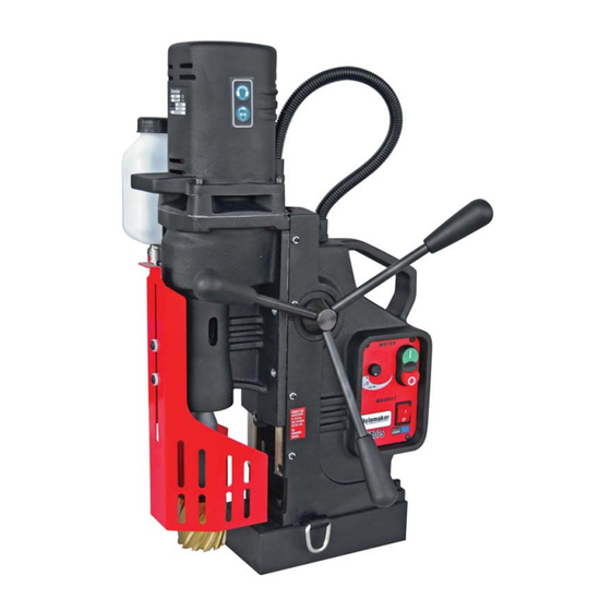
Holemaker Portable Magnetic Drilling Machine
OPERATOR'S MANUAL
BEFORE USE
EYE PROTECTION
REQUIRED
S
r e
a i
# l
VER: 1.10
01/09/15
WARNING!
,
ENSURE EVERYONE USING THIS MACHINE READS AND UNDERSTANDS
ALL SAFETY AND OPERATING INSTRUCTIONS IN THIS MANUAL
HEARING PROTECTION
REQUIRED
CUTTING AREA OR
MACHINE ARBOR
NEVER PLACE
LINE VOLTAGE
FINGERS NEAR
PRESENT
D
a
e t
f o
P
.
BEWARE OF
ROTATING
MACHINE PARTS
SWIVEL BASE
& REVERSIBLE
r u
h c
a
e s
Advertisement
Table of Contents

Related Manuals for Itm HOLEMAKER PRO 75 SR


Summary of Contents for Itm HOLEMAKER PRO 75 SR
- Page 1 HOLEMAKER PRO 75 SR Holemaker Portable Magnetic Drilling Machine OPERATOR’S MANUAL WARNING! BEFORE USE ENSURE EVERYONE USING THIS MACHINE READS AND UNDERSTANDS ALL SAFETY AND OPERATING INSTRUCTIONS IN THIS MANUAL EYE PROTECTION HEARING PROTECTION NEVER PLACE LINE VOLTAGE BEWARE OF...
-
Page 2: Table Of Contents
Holemaker PRO 75 SR Portable Magnetic Drilling Machine Congratulations on the purchase of your Holemaker Pro 75 SR portable magnetic drilling machine. Holemaker drilling machines are designed to deliver fast, efficient hole drilling performance in portable applications. TABLE OF CONTENTS Important Safety Instructions . -
Page 3: Important Safety Instructions
IMPORTANT SAFETY INSTRUCTIONS WARNING! WHEN USING ELECTRICAL TOOLS BASIC SAFETY PRECAUTIONS SHOULD ALWAYS BE FOLLOWED TO REDUCE RISK OF FIRE ELECTRIC SHOCK AND PERSONAL INJURY READ AND SAVE ALL INSTRUCTIONS FOR FUTURE REFERENCE. 1. Keep Work Area Clean • Cluttered areas and benches increase risk of injuries. 2. - Page 4 IMPORTANT SAFETY INSTRUCTIONS 12. Maintain Tools With Care • Keep tools sharp and clean for better and safer performance. • Follow instructions for lubricating and changing accessories. • Inspect tool cords periodically and if damaged, have repaired by authorized service facility. •...
-
Page 5: Power Supply Requirement
POWER SUPPLY REQUIREMENTS Prior to use check condition of the power cord, which has to be free of any cuts, or similar damages. Attention!: This unit has a class one of insulation and absolutely requires the power source to be equipped with a protection circuit. -
Page 6: Technical Data
TECHNICAL DATA Supply voltage: ………………………………… 220-240V/ 50-60 Hz. Motor power ……………………………………………………. 1650 W Total power …………………………………………………….. 1800 W Machine speeds (under load): ………………..Gear 1: 80-160rpm Gear 2: 210-420rpm Insulation class ………………………………………………….. First Arbor bore ………………………………………………………. MT 3 Tool holder …………………………………. "... -
Page 7: Special Instructions
SPECIAL INSTRUCTIONS 1. Read and follow operator’s manual thoroughly. 2. DO NOT touch rotating cutter or parts. 3. Always stop machine completely and unplug from power source before changing cutters, clearing swarf, refilling lubrication or performing adjustments. 4. Never wear loose clothing or gloves when working near cutting area or machine arbor. 5. -
Page 8: Start-Up And Operation
START UP AND OPERATION CAUTION: READ THE WHOLE INSTRUCTIONS MANUAL BEFORE ATTEMPTING TO START UP Principle of Annular cutter’s work This drilling machine’s spindle has a 19mm Weldon Shank type and is specifically designed for use with Annular cutters. Annular cutter (1) is located inside arbor body (2) and is fastened with grub screws (3). When fastening the cutter in the arbour, ensure that the grub screws are firmly tightened to avoid them coming loose during operation. - Page 9 Before you cut Before positioning the machine on work piece always make sure that: - work piece is made of ferrous material - thickness of work piece is adequate for secure magnetic adhesion (mild steel - 10mm is recommended) - Ensure no part of magnet overhangs the steel workpiece - surface of steel under the magnet is flat - wipe, brush or sand down clean surface where you intended to place the drilling machine, so that you remove rust, paint, dirt etc which would reduce adhesive...
- Page 10 Cutting - Choose a suitable lubricating fluid and fill the coolant tank. The cooling system is an integral part of the machine and should always be used. Warning: The cooling system works gravitationally, therefore it can be used only when in vertical position of the drilling machine. In other positions, a cutting paste should be used - Check workings of cooling system.
-
Page 11: Maintenance And Service
MAINTENANCE AND SERVICE - Every 250 hours of work check condition of carbon brushes. If their length is less than 5 mm they should be replaced with new genuine brushes. After replacement, new brushes should be run-in without load for about 20 min. Repair and service work is to be performed by authorized service agents only. -
Page 12: Basic Troubleshooting
BASIC TROUBLESHOOTING 1. Magnetic base not holding securely • Material is too thin. • Surface of material being drilled must be free of chips, debris, rust and mill scale. • Does size of cutter exceed machine’s rated capacity? • Check magnet face for unevenness, nicks and burrs. 2. -
Page 13: Parts List
PARTS LIST HMPRO75 MAGNETIC DRILLING MACHINE HOLEMAKER PRO 75 ITEM PART NUMBER SPPRO750115 FRAME SPPRO75201 MOTOR COMPLETE /230V SPPRO7503 PANEL PLATE ASSY SPPRO7504 GUARD ASSY SPPRO7505 PINION SHAFT ASSY SPPRO75061 ELECTRONIC CONTROL SYSTEM /230V SPPRO7507 SPOKE HANDLE INCLUDING KNOB (ASSY) SPPRO3509 LOWER SLEEVE, SPPRO5012... - Page 14 ITEM PART NUMBER SPPRO750115 MAIN BODY SPPRO750102 D-RING STRAP SPPRO750103 ELECTROMAGNETIC BASE SPPRO755104 SWIVEL BASE PLATE SPPRO755105 CLAMPING PLATE ARM SPPRO755106 ECCENTRIC SWIVEL BASE SHAFT SPPRO755107 SPECIAL NUT SPPRO755108 SPECIAL WASHER MT3 V2 SPPRO755109 SPECIAL BOLT , SPPRO7550110 EXTERNAL RETAINING RING- 21Z SPPRO750111 SPRING WASHER 6,1 SPPRO750112...
- Page 15 ITEM PART NUMBER SPPRO750115 MAIN BODY SPPRO750112 PRESSURE PLATE SPPRO750113 SLIDE INSERT SPPRO75010104 SELF LUBRICATING SLEEVE 28,05H7x32x16, SPPRO75010105 SPRING WASHER SPPRO500116 DISC SPRING 4,2x10x0,5 SPPRO75010107 HEX SOCKET BOLT-M5X20 SPPRO75010108 ROUND WASHER 5,3 SPPRO75010109 SELF LUBRICATING SLEEVE 21H7-24-16, SPHM40110 NUT M5 SPHM40109 SOCKET SET SCREW M5x16,...
- Page 16 ITEM PART NUMBER SPPRO750201 MOTOR ASSY/230V SPPRO750202 GEARCASE ASSY SPPRO750203 PINION SHAFT z12, m=1, z24, m=1 ASSY SPPRO750204 PINION SHAFT z12, m=1,5 ASSY MOTOR HOUSING SPPRO750205 SPPRO750206 GEAR z50 SPPRO750207 MOTOR WIRE ASSY SPPRO750208 GEAR RACK SPPRO750209 ENCODER FRAME SPPRO750210 ENCODER MODULE SPPRO750212 NEUTRAL MOTOR WIRE ASSY...
- Page 18 ITEM PART NUMBER SPPRO75020101 MOTOR COVER SPPRO50020102 GUIDE FAN SPPRO75020103 ARMATURE ASSY /230V SPPRO75020104 ARMATURE TOOTH END z8 SPPRO75020105 FIELD /230V SPPRO75020106 UPPER HOUSING SPPRO75020107 CROSS RECESSED PAN HEAD TAPPING SCREW 4x16 SPPRO75020108 SPRING WASHER SPPRO50020109 BRUSH /230V SPPRO50020110 SPRING BRUSH SPPRO75020111 HEXAGON BOLT M4X73...
- Page 19 ITEM PART NUMBER SPPRO75020201 GEARCASE SPPRO75020202 SPINDLE SPPRO75020203 COOLANT COUPLING AMT2-H-19 SPPRO75020204 UPPER SPINDLE BEARING 6000 2Z P6 S 10x26x8, SPPRO75020205 UPPER SPINDLE BEARING 6007 ZZ 35x62x14, SPPRO75020206 BEARING 6205 LLU 25x51x15 SPPRO75020207 SEAL 35x55x10 SP4805 SEAL 35x56x12 SPPRO75020209 EXTERNAL RETAINING RING- 35Z SPPRO75020210 INTERNAL RETAINING RING 62W SPPRO75020211...
- Page 20 ITEM PART NUMBER DESCRIPTION SPPRO75020301 PINION SHAFT z12, m=1, z24, m=1 SPPRO75020302 HELICAL INPUT GEAR z47, m=1, m=17 SPPRO75020303 WOODRUFF KEY 3x3.7 BE628 UPPER SPINDLE BEARING 628 2Z NTN 8x24x8 ITEM PART NUMBER DESCRIPTION SPPRO75020401 PINION SHAFT z12, m=1,5 SPPRO75020402 SHIFT WHEEL z=43 SPPRO75020403 KEY 4x4x45...
- Page 21 ITEM PART NUMBER DESCRIPTION SPPRO750301 PANEL PLATE SPPRO75033 SWITCH START-STOP, SPPRO750304 SWITCH CONTACT BLOCK SPHM300405 SWITCH MAGNET SPPRO75036 SPEED CONTROL SWITCH SPPRO75SR47 FORWARD REVERSE SWITCH...
-
Page 23: Electrical Diagram
ELECTRICAL DIAGRAM...
Need help?
Do you have a question about the HOLEMAKER PRO 75 SR and is the answer not in the manual?
Questions and answers
How do I remove magnet from homemaker pro75