Table of Contents
Advertisement
Quick Links
No: 33527 – 10/24 rev. 2
Catalog Numbers • Les Numéros de Catalogue • Los Números de Catálogo: LMJA-9125-SM, LMJA-9300-SM
Country of Origin: Made in Slovakia • Pays d'origine: Fabriqué en Slovaquie • País de origen: Hecho en Eslovaquia
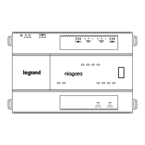
Wattstopper offers two JACE 9000 network controllers that provide
advanced building management and automation features for customers
using Digital Lighting Management (DLM) BACnet-based networks and
devices—the LMJA-9125-SM and LMJA-9300-SM. These units (referred to
as LMJA-9xxx-SM) use the same hardware and are powered by the Tridium
N4 Niagara platform, the only difference being the number of control points
they are licensed for. The controllers also include the Segment Manager (or
Segman) Station - an easy-to-use interface for DLM product configuration.
When used with a DLM wired or wireless network segments the LMJA-
9xxx-SM series network controllers provide global control, monitoring,
adjustment, scheduling, and support for custom graphics. Larger buildings
and campus deployments with multiple network controllers can also
communicate to a "Supervisor" software package for a single point of
BACnet management and monitoring. The LMJA-9xxx-SM series can be
configured to work with just the DLM platform or can be integrated into an
existing 3rd party Building Management System (BMS).
Unpack the LMJA-9125-SM/9300-SM controller and power module and inspect the package contents for damaged or missing
components. If damaged, notify the appropriate carrier at once and return any damaged components for immediate repair or
replacement.
Included in this Package
Included in this package you should find the following items:
• (1) DLM LMJA-9xxx-SM controller unit with micro SD card
• (1) Controller power supply receptacle power supply (Cat # NB-PS1)
• (1) Wattstopper DLM quick reference guide
• (1) Wattstopper installation sheet (#33527)
• (1) Accessory wiring and connector accessory pack
Safety Precautions
The following items are warnings of a general nature relating to the installation and start-up of the LMJA-9xxx-SM. Be sure to heed
these warnings to prevent personal injury or equipment damage.
WARNING
• Disconnect power before installation or servicing to prevent electrical shock or equipment damage.
• Make all connections in accordance with national and local electrical codes. Use copper conductors only.
• To reduce the risk of fire or electrical shock, install in a controlled environment relatively free of contaminants.
• This device is only intended for use as a monitoring and control device. To prevent data loss or equipment damage, do not use it
for any other purpose.
Static Discharge Precautions
Static charges produce voltages high enough to damage electronic components. The microprocessors and associated circuitry within a
Segment Manager are sensitive to static discharge. Follow these precautions when installing, servicing, or operating the system:
CAUTION
• Work in a static-free area.
• Discharge any static electricity you may have accumulated. Discharge static electricity by touching a securely grounded object.
• Do not handle the printed circuit board (PCB) without proper protection against static discharge. Use a wrist strap when handling
PCBs. The wrist strap clamp must be secured to earth ground.
OVERVIEW
Wattstopper
DLM LMJA-9xxx-SM Network Controller with Segment Manager
Station
Installation Instructions • Instructions d'Installation • Instrucciones de Instalación
PREPARATION
1
®
CAUTION
Advertisement
Table of Contents

Subscribe to Our Youtube Channel
Related Manuals for LEGRAND Wattstopper LMJA-9-SM Series


Summary of Contents for LEGRAND Wattstopper LMJA-9-SM Series
- Page 1 Wattstopper ® DLM LMJA-9xxx-SM Network Controller with Segment Manager Station No: 33527 – 10/24 rev. 2 Installation Instructions • Instructions d’Installation • Instrucciones de Instalación Catalog Numbers • Les Numéros de Catalogue • Los Números de Catálogo: LMJA-9125-SM, LMJA-9300-SM Country of Origin: Made in Slovakia • Pays d’origine: Fabriqué en Slovaquie • País de origen: Hecho en Eslovaquia OVERVIEW Wattstopper offers two JACE 9000 network controllers that provide advanced building management and automation features for customers...
-
Page 2: Material And Tools Required
Inserting or Removing the Micro SD Card Installation Before mounting a new controller, you must insert the included microSD flash memory card. Note the card has the unique Niagara identity (host ID) for the unit, set at the factory. ALL power to the controller must be removed. If the unit is currently running, initiate a controller shutdown. -
Page 3: Physical Mounting
Physical Mounting The following information applies to physically mounting the unit. • You can mount the LMJA-9xxx-SM in any orientation. Horizontal mounting (as shown) is strongly recommended to achieve maximum heat dissipation and meet the operating temperature upper limit. Any other mounting orientation reduces this upper limit. •... -
Page 4: Tab Mounting Dimensions
DIN Rail Mounting Dimensions This diagram shows mounting dimensions of controller and option modules. Electronic and printed versions of this guide may not show the dimensions to scale. Verify all measurements before drilling. Optional RS-485 7.05” (179mm) Module 2.26” (57.5mm) 6.38”... -
Page 5: Power Wiring
Power Wiring The LMJA-9xxx-SM must be powered by an approved 24VDC power source. This can be either an external wall mount AC adapter (NB- PS1), or other source of 24 volts DC. The LMJA-9xxx-SM does not have an on/off switch. To apply power, plug in to either the Barrel power connector (1) or 2 position plug (2). Do not plug the power supply connector into the LMJA-9xxx-SM CAUTION controller until all other mounting and wiring is completed. -
Page 6: Communications Wiring
Then insert the end of the ferrule into the appropriate slot in the terminal block. LM-MSTP wire Jacket Bare Wire Crimp Insulation Insulation Strip Guide Attaching a Ferrule *Legrand recommends using Ferrules, but if not using, wire should be stripped to .25” only... - Page 7 S (Shield) NOTE: R = S Terminals on Tridium hardware for – Wattstopper wiring. Wattstopper uses a 3-wire S (R) conductor plus shield (LM-MSTP) for all installations. The shield is terminated to ground typically at the network controller. RS485-A LMJA-IO-R-34 LMJA-IO-R-34 OUT TO SEGMENT NETWORK (Shield)
-
Page 8: Power Up And Initial Checkout
POWER UP AND INITIAL CHECKOUT Ensure power wiring to the LMJA-9xxx-SM is ready—see the “Wiring: Earth Ground and Power” section. Refer to page 10 for the locations of the power connections. After mounting and wiring, perform the following: Step 1 Apply Power •... -
Page 9: Ethernet Ports
If the STATUS LED is not lit while power is applied, contact Wattstopper Technical Support. Heartbeat The “BEAT” LED is located to the right of the Ethernet LEDs, and is yellow. Under normal operation, this LED should blink about once per second. - Page 10 USB PORT AND SHUTDOWN SWITCH Behind the controller’s front access door is a USB-C debug port, a pushbutton shutdown switch, and an associated LED. – SHUTDOWN – DEBUG S H U T D O The DEBUG port is a USB-C port for serial debug communications to the controller only.. You can use a serial terminal program (for example: PuTTY) to access the controller’s “system shell”...
-
Page 11: End User License Agreement
END USER LICENSE AGREEMENT “In order to enhance the security of our products, Legrand ships its products with all insecure ports closed and insecure protocols disabled. You are free to configure your device as needed, but in doing so note that you may be decreasing the security of your device and any information contained in the device. - Page 12 6. Click Properties. 7. Select Use the following IP address. 8. Enter the IP address and Subnet mask. Set the PC to 192.168.1.xxx (where xxx is any number between 001 and 255 and is not the same as the Segment Manager). Set the subnet mask to 255.255.255.0. 9.
-
Page 13: Wiring Examples
WIRING EXAMPLES The following pages display some examples of various connection scenarios. LMJA-9xxx-SM The LMJA-9xxx-SM can connect to up to two separate segments, and is used for buildings in which there is no more than 120 rooms (controlled by the LMBC-300 bridge) or common areas (controlled by a panel or zone controller). EXAMPLE: A Single network segment with 40 or fewer rooms/common spaces NOTE: Follow wiring details in Wattstopper Submittal regarding reference wire, shield ground, and terminating resistors. - Page 14 EXAMPLE: Four story building with some floors having more than 40 rooms/common spaces NOTE: Follow wiring details in Wattstopper Submittal regarding reference wire, shield ground, and terminating resistors. The LMJA-9xxx-SM can be used in conjunction with multiple NB-Routers and an NB-Switch. These components are usually housed inside an LMNC DLM Network Component Enclosure.
- Page 15 EXAMPLE: Two LMJA-9xxxs - Example of a 10 story building with no more than 40 rooms/common spaces per floor In larger buildings with more floors and/or more than 300 rooms/spaces, multiple segment managers are used and connected via Ethernet. NOTE: Follow wiring details in Wattstopper Submittal regarding reference wire, shield ground, and terminating resistors. LMNC-5 (With 5 routers and a 16 port switch) Located on 6th floor Ethernet...
- Page 16 WIRING EXAMPLE - WIRELESS Example of a Multi-Story Building with a Wireless Network with Wired or Hybrid Rooms In larger buildings with more floors and/or more than 300 rooms/spaces, multiple segment managers are used and connected via Ethernet. Wireless networking between rooms is handled by the LMBR-650 Border Router. The LMBR-650 border router acts as a management and gateway device for IPv6 Mesh wireless network bridges.
- Page 17 WIRING EXAMPLES - HYBRID Example of a hybrid 4 story building with no more than 40 rooms/common spaces per floor In larger buildings with more floors and/or more than 300 rooms/spaces, multiple segment managers are used and connected via Ethernet. NOTE: Follow wiring details in Wattstopper Submittal regarding reference wire, shield ground, and terminating resistors.
- Page 18 DEVICE POINTS AND LIMITS DEVICE POINTS / LIMITS LMJA-9125-SM LMJA-9300-SM Maximum # of Room/Bridges Maximum Total # of Devices per LMJA-9xxx 2000 2000 Maximum # of Wired MS/TP Segments With LMJA-NPB-2X-485, the wired MS/TP Segments are expandable to: Maximum # of LMBC-300 per Segment Recommended # of IP Segments Using NB-ROUTER Maximum # of Wireless IP LMBR’s Segments Maximum # of Devices per Segment...
- Page 19 MULTI-LINE DRAWINGS AND DIMENSIONS 6.375” (162mm) 2.26” (57.5mm) 4.375” 2.13” (54mm) (101.6mm) LEFT SIDE FRONT RIGHT SIDE BACK BOTTOM...
- Page 20 No. 33527 – 10/24 rev. 2 © Copyright 2024 Legrand All Rights Reserved. 800.879.8585 © Copyright 2024 Tous droits réservés Legrand. www.legrand.us/wattstopper © Copyright 2024 Legrand Todos los derechos reservados.
Need help?
Do you have a question about the Wattstopper LMJA-9-SM Series and is the answer not in the manual?
Questions and answers