Table of Contents
Advertisement
Available languages
Available languages
No: 22893 – 11/17 rev. 2
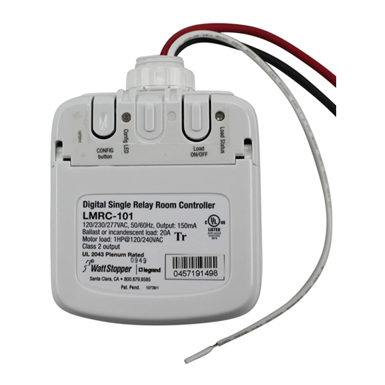
Catalog Number • Numéro de Catalogue • Número de Catálogo: LMRC-101
Country of Origin: Made in China • Pays d'origine: Fabriqué en Chine • País de origen: Hecho en China
This unit is pre-set for Plug n' Go™ operation, adjustment is optional.
For full operational details, adjustment and more features of the product, see the
DLM System Installation Guide provided with Wattstopper room controllers, and also
available at www.legrand.us/wattstopper.
Installation shall be in accordance with all applicable regulations, local and NEC
codes. Wire connections shall be rated suitable for the wire size (lead and building
wiring) employed.
For Class 2 DLM devices and device wiring: To be connected to a Class 2 power
source only. Do not reclassify and install as Class 1, or Power and Lighting Wiring.
WARNING: Do not install to cover a junction box having Class 1, 3 or Power and
Lighting Circuits.
Corner Mount
Occupancy
Sensor
Daylighting
J Box
Sensor
Ceiling Mount
Occupancy
Sensor
MOUNTING THE CONTROLLER
The LMRC‑101 room controller can be mounted external to either
a 4"x 4" or 4‑11/16 x 4‑11/16 junction box, placing it in the plenum
space or mounted directly inside a 4‑11/16 x 4‑11/16 junction box.
Outside a 4" x 4" or
4 11/16 x 4‑11/16 box
PLACEMENT EXAMPLE
DLM Local Network
(low voltage, Class 2)
LMRJ cables
Room
Controller
To
Load
J-Box
Inside a 4 11/16 x 4‑11/16 box
Wattstopper
Digital Lighting Management Single Relay Room Controller
Gestion numérique de l'éclairage Contrôleur de pièce à relais unique
Control de la iluminación digital Controlador de habitación de relé simple
Quick Start Guide • Guide de démarrage rapide • Guía de inicio rápido
DLM LOCAL NETWORK USE THE LMCI-100. NEVER
COMPUTERS AND OTHER CONNECTED EQUIPMENT.
Switch
J-Boxes
Remove rubber jack covers if using all 3 RJ45 receptacles.
Leave covers in place for all unused receptacles.
®
SPECIFICATIONS
Input Voltage ....... Single Phase 120/230/240/277VAC, 50/60Hz
Load Requirements
Incandescent ........................................20A @ 120VAC
Ballast ...........................................20A @ 120/277VAC
Motor ............................................ 1Hp @ 120/240VAC
Output ....................................................... 150mA @ 24VDC
DLM Local Network Characteristics:
Provides low voltage power over Cat 5e cable (LMRJ).
Supports up to 24 communicating devices, including 4
LMRC‑10x or LMPL‑101 max per each DLM Local Network.
Free topology up to 1,000ft of low voltage cable.
Environment:
Operating Temperature .........32° to 104°F (0° to 40°C)
Storage Temperature ...........23° to 176°F (‑5° to 80°C)
Relative Humidity ...............5 to 95% (non condensing)
Patent Pending
WARNING: TURN THE
POWER OFF AT THE CIRCUIT
BREAKER BEFORE WIRING.
CAUTION: TO CONNECT A COMPUTER TO THE
CONNECT THE DLM LOCAL NETWORK
TO AN ETHERNET PORT – IT MAY DAMAGE
ATTACHING CABLES
Advertisement
Table of Contents

Related Manuals for LEGRAND Wattstopper LMRC-101


Summary of Contents for LEGRAND Wattstopper LMRC-101
- Page 1 LMRC‑10x or LMPL‑101 max per each DLM Local Network. DLM System Installation Guide provided with Wattstopper room controllers, and also Free topology up to 1,000ft of low voltage cable. available at www.legrand.us/wattstopper. Environment: Installation shall be in accordance with all applicable regulations, local and NEC Operating Temperature ..32°...
- Page 2 CONNECTIVITY Ceiling Mount The LMRC‑101 communicates to all other DLM devices connected to the Line Sensor Voltage DLM Local Network. Connection drawings are for example only. The low DLM Local Network voltage LMRJ cables can connect to any DLM device with an open RJ45 Low Voltage receptacle.
- Page 3 Incandescence ...........20 A à 120 VCA DLM fourni avec Wattstopper contrôleurs de pièce et aussi disponible au Ballast ............20 A à 120/277 VCA www.legrand.us/wattstopper. Moteur ............1 Hp à 120/240 VCA Sortie ..............150 mA à 24 VCC L'installation doit être effectuée conformément à tous les règlements Caractéristiques du réseau local DLM :...
- Page 4 MONTAGE LE CONTRÔLEUR Le contrôleur de pièce LMRC‑101 peut être monté de manière externe avec une boîte de jonction de 10,2 cm x 10,2 cm (4 po x 4 po) ou de 11,9 cm x 11,9 cm (4‑11/16 po x 4‑11/16 po) en le plaçant dans l’espacement ou en l’installant directement à l’intérieur d’une boîte de jonction de 11,9 cm x 11,9 cm (4‑11/16 po x 4‑11/16 po).
- Page 5 RÉGLAGE DE L’APPAREIL OPTIONNEL - PUSH N’ LEARN (PNL) Procédure de sélection de la charge Un bouton de configuration (config) permet d’accéder à notre technologie brevetée Push n’ Learn pour modifier les liens entre les détecteurs, les interrupteurs et les charges. Étape1 Entrer en mode Push n’...
- Page 6 Motor ............1 HP a 120/240 V CA proporciona con los controladores de habitación Wattstopper; también Salida ..............150 mA a 24 V CC está disponible en www.legrand.us/wattstopper. Características de red local DLM: Suministra alimentación de bajo voltaje por un cable Cat 5e (LMRJ).
- Page 7 CONECTIVIDAD Sensor de El dispositivo LMRC‑101 se comunica con todos los demás dispositivos Ocupación de DLM conectados a la red local DLM. Los esquemas de conexiones que Voltaje Montaje en Techo de línea se muestran son únicamente a modo de ejemplo. Los cables LMRJ de Cables LMRJ de Red Local DLM bajo voltaje se pueden conectar a cualquier dispositivo DLM con un...
- Page 8 No. 22893 – 11/17 rev. 2 © Copyright 2017 Legrand All Rights Reserved. 800.879.8585 © Copyright 2017 Tous droits réservés Legrand. www.legrand.us/wattstopper © Copyright 2017 Legrand Todos los derechos reservados.
Need help?
Do you have a question about the Wattstopper LMRC-101 and is the answer not in the manual?
Questions and answers
is there a occupancy sensor that mounts to a single gang switch plate that can be used with theLMRC
Yes, the context mentions a "Switch Sensor" and a "Corner Mount Occupancy Sensor" as compatible with the LMRC-101. The "Switch Sensor" implies a design suitable for mounting to a switch plate, which typically fits a single gang box. Therefore, an occupancy sensor compatible with the LMRC-101 that mounts to a single gang switch plate is available.
This answer is automatically generated