Advertisement
Table of Contents
- 1 Material and Tools Required
- 2 Environmental Requirements
- 3 Physical Mounting
- 4 Tab Mounting Dimensions
- 5 Static Ip Address Setup
- 6 Using Status Leds
- 7 Ethernet Ports
- 8 Communications Wiring
- 9 Wiring Details
- 10 Power Wiring
- 11 Power up and Initial Checkout
- 12 Wiring Examples
- 13 Warranty Information
- 14 Información de la Garantía
- Download this manual
No: 28957 – 8/19 rev. 2
Catalog Numbers • Les Nombre de Catalogue • Números de Catálogo: LMJA-8125, LMJA-8300/LMJA-8125-AX, LMJA-8300-AX
Country of Origin: Made in China • Pays d'origine: Fabriqué en Chine • País de origen: Hecho en China
The Legrand/Wattstopper LMJA-8125/LMJA-8300 is a network controller
that provides advanced building management and automation features for
customers using Digital Lighting Management (DLM) BACnet-based networks
and devices. Powered by the Tridium Niagara platform, the controller can
be ordered with either the N4 or AX 3.8 (LMJA-8xxx-AX) Segman 2.4
station. The LMJA-8xxx Network controller hardware running are licensed
for use with Wattstopper DLM. When used with a DLM wired or wireless
network segments the LMJA-8xxx series network controllers provide global
control, monitoring, adjustment, scheduling, and support for graphics. Larger
buildings and campus deployments with multiple network controllers can
also communicate to a supervisor software for a single point of BACnet
management and monitoring. The LMJA-8xxx series can be configured to
work with just DLM platform or can be integrated into an existing 3rd party
Building Management System (BMS).
Unpack the LMJA-8125/8300 controller and power module and inspect the package contents for damaged or missing components. If
damaged, notify the appropriate carrier at once and return any damaged components for immediate repair or replacement.
Included in this Package
Included in this package you should find the following items:
• (1) DLM LMJA-8125/8300 controller unit with micro SD card
• (1) Controller power supply
• (1) Wattstopper DLM quick reference guide
• (1) Wattstopper installation sheet (28957)
• (1) Accessory wiring and connector accessory pack
Safety Precautions
The following items are warnings of a general nature relating to the installation and start-up of the LMJA-8xxx. Be sure to heed these
warnings to prevent personal injury or equipment damage.
WARNING
• Disconnect power before installation or servicing to prevent electrical shock or equipment damage.
• Make all connections in accordance with national and local electrical codes. Use copper conductors only.
• To reduce the risk of fire or electrical shock, install in a controlled environment relatively free of contaminants.
• This device is only intended for use as a monitoring and control device. To prevent data loss or equipment damage, do not
use it for any other purpose.
Static Discharge Precautions
Static charges produce voltages high enough to damage electronic components. The microprocessors and associated circuitry within a
Segment Manager are sensitive to static discharge. Follow these precautions when installing, servicing, or operating the system:
CAUTION
• Work in a static-free area.
• Discharge any static electricity you may have accumulated. Discharge static electricity by touching a securely grounded
object.
• Do not handle the printed circuit board (PCB) without proper protection against static discharge. Use a wrist strap when
handling PCBs. The wrist strap clamp must be secured to earth ground.
OVERVIEW
Wattstopper
DLM LMJA-8xxx Network Controller
Installation Instructions • Instructions d'Installation • Instrucciones de Instalación
PREPARATION
CAUTION
1
®
Advertisement
Table of Contents

Related Manuals for LEGRAND Wattstopper DLM LMJA-8 Series


Summary of Contents for LEGRAND Wattstopper DLM LMJA-8 Series
- Page 1 Country of Origin: Made in China • Pays d’origine: Fabriqué en Chine • País de origen: Hecho en China OVERVIEW The Legrand/Wattstopper LMJA-8125/LMJA-8300 is a network controller that provides advanced building management and automation features for customers using Digital Lighting Management (DLM) BACnet-based networks and devices.
-
Page 2: Material And Tools Required
PREPARATION (continued) Inserting or Removing the Micro SD Card Installation Before mounting a new controller, you must insert the included microSD flash memory card. Note the card has the unique Niagara identity (host ID) for the unit, set at the factory. ALL power to the controller must be removed. If the unit is currently running, initiate a controller shutdown. -
Page 3: Physical Mounting
MOUNTING (continued) Physical Mounting The following information applies to physically mounting the unit. • You can mount the LMJA-8125/8300 in any orientation. Horizontal mounting (as shown) is strongly recommended to achieve maximum heat dissipation and meet the operating temperature upper limit. Any other mounting orientation reduces this upper limit. •... -
Page 4: Tab Mounting Dimensions
MOUNTING (continued) DIN Rail Mounting Dimensions This diagram shows mounting dimensions of controller and option modules. Electronic and printed versions of this guide may not show the dimensions to scale. Verify all measurements before drilling. Tab Mounting Dimensions Measurements shown below are in inches and (mm). NOTE: DIN rail mounting is recommended over tab mounting. The LMJA-8125/8300 controller. - Page 5 INITIAL LOGIN AND SET UP - AX 3.8 (SEGMAN 2.4) Make sure that you have followed all installation instructions and that the controller is properly powered and connected to the segment network(s). 1. Connect a PC to the LAN 1 connection on the LMJA-8xxx-AX using a standard Ethernet cable (not supplied). Note that some older PCs require the use of a crossover cable for this connection.
-
Page 6: Static Ip Address Setup
STATIC IP ADDRESS SETUP These instructions apply to Windows 7, 8, or 10. Consult the appropriate documentation for other operating systems. ® To set up the computer for direct connection to the Segment Manager, proceed as follows: 1. Click on the Start menu and type: network sharing center. Then Click on “Network and Sharing Center” in results. 2. - Page 7 STATIC IP ADDRESS SETUP (continued) 4. Click Properties. 5. Select Use the following IP address. 6. Enter the IP address and Subnet mask. Set the PC to 192.168.1.xxx (where xxx is any number between 001 and 255 and is not the same as the Segment Manager).
-
Page 8: Using Status Leds
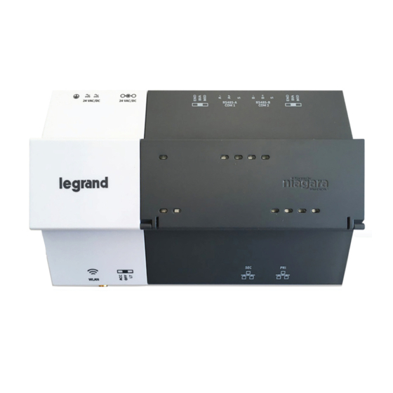
STATUS LEDS The controller provides a number of status LEDs, with all but one visible with the front access door closed. WiFi (green) - This option is not used RS485 “A” (COM1) - Transmit (TX, Yellow) and Receive (RX, Green) RS485 “B”... - Page 9 USING STATUS LEDS (continued) RS485 LEDs RS485 port A (Com1) and RS495 port B (COM2) each have two LEDs reflecting port activity as follows: • Yellow (TX): Indicates the controller is transmitting data on the RS485 port • Green (RX): Indicates the controller is receiving data from an RS485 device connected to this port These LEDs use a fixed “on time”...
- Page 10 USB PORTS AND PUSHBUTTON SWITCHES Behind the controller’s front access door are two USB ports, two pushbutton switches, and an associated LED. PROG - USB 2.0 for usage with USB flash drive DEBUG - Micro-A USB for serial debug communications BACKUP - Pushbutton switch to start a USB backup, or if held in during power up/boot up, a factory recovery image SHT/DWN - Recessed switch for controlled shutdown BACKUP - LED to indicate USB media present, or a backup, restore, or factory recovery image in progress...
-
Page 11: Communications Wiring
COMMUNICATIONS WIRING Ports for field communications are shown on controller. RS485 ports and bias switches Ethernet ports, 10/100-Mbit, RJ-45 Earth ground and 24V power input WLAN is NOT enabled (RS485-A (RS485-B COM 1) COM 2) (EN1 or (EN0 or LAN2) LAN1) - Page 12 WIRING: RS485 On the controller’s top side, two RS485 ports operate as COM1 and COM2. Each port is capable of up to 115,200 baud, and uses a 3-position, screw terminal connector. RS485 port A (COM1) is often used to support a LMJA-IO-R-34 module. NOTE: Do not mix LMJA-IO-R-34 modules with other types of RS485 devices on the same RS485 trunk.
-
Page 13: Wiring Details
WIRING DETAILS Make connections to the controller in the following order: 1. Connect supplied earth grounding wires (with spade connector) from the earth ground lug on the controller to a nearby earth grounding point. See “Wiring: Earth Ground and Power” for details. 2. - Page 14 Insulation Insulation Strip Guide Attaching a Ferrule *Legrand recommends using Ferrules, but if not using, wire should be stripped to .25” only Ethernet Two female 10/100-Mbit Ethernet connections are provided on the LMJA-8125/8300. These are RJ-45 connectors labeled SEC and PRI.
-
Page 15: Power Up And Initial Checkout
POWER UP AND INITIAL CHECKOUT Ensure power wiring to the LMJA-8xxx is ready—see the “Wiring: Earth Ground and Power” section. Refer to page 10 for the locations of the power connections. After mounting and wiring, perform the following: Step 1: Apply Power •... - Page 16 WIRING EXAMPLES (continued) EXAMPLE: Three story building with no more than 40 rooms/common spaces per floor 3rd Floor Daisy-chain to LMBC/LMCP/LMZCs NO MORE THAN 40 TOTAL LMBC-300 LMBC-300 LMBC-300 Segment Networks 1, 2, and 3 2nd Floor Daisy-chain to LMBC/LMCP/LMZCs NO MORE THAN 40 TOTAL LMBC-300 LMBC-300...
- Page 17 WIRING EXAMPLES (continued) EXAMPLE: Two LMJA-8xxxs - Example of a 10 story building with no more than 40 rooms/common spaces per floor In larger buildings with more floors and/or more than 300 rooms/spaces, multiple segment managers are used and connected via Ethernet. LMNC-5 (With 5 routers and a 16 port switch) Located on 6th floor Ethernet...
- Page 18 Option 2 may not be as secure as Option 1, since it is completely dependent on the customer-provided and managed devices for network security. LEGRAND ASSUMES NO RESPONSIBILITY OR LIABILITY FOR A SECURITY FAILURE. YOUR FAILURE TO IMPLEMENT THESE MANDATORY SECURITY STEPS MAY EXPOSE YOU TO LIABILITY IN THE EVENT OF A BREACH.
- Page 19 WIRING EXAMPLES - HYBRID Example of a hybrid 4 story building with no more than 40 rooms/common spaces per floor In larger buildings with more floors and/or more than 300 rooms/spaces, multiple segment managers are used and connected via Ethernet. LMNC Ethernet LMBC-300, LMCP, or LMZC-301...
- Page 20 CERTIFICATIONS Federal Communications Commission (FCC) This device complies with Part 15 of the FCC Rules. Operation is subject to the following two conditions: This device may not cause harmful interference, and This device must accept any interference received, including interference that may cause undesired operation Changes or modifications not expressly approved by the part responsible for compliance could void the user’s authority to operate the equipment.
- Page 21 CERTIFICATIONS (continued) EMC Standards Applied Standard Description Criteria Met EN 61000-6-4 Electro-Magnetic Compatibility Emissions Generic Complies EN 61000-6-2 and Electro-Magnetic Compatibility Immunity Complies EN 61000-6-1 EN50081-2 Generic Emission Standard for residential, commercial, and light industrial environment CISPR 11 Limits of Radio Disturbance - Radiated Emissions PASS Class A Limits of Radio Disturbance - Conducted Emissions PASS Class A...
-
Page 22: Warranty Information
No. 28957 – 8/19 rev. 2 © Copyright 2019 Legrand All Rights Reserved. 800.879.8585 © Copyright 2019 Tous droits réservés Legrand. www.legrand.us/wattstopper © Copyright 2019 Legrand Todos los derechos reservados.
Need help?
Do you have a question about the Wattstopper DLM LMJA-8 Series and is the answer not in the manual?
Questions and answers