Table of Contents
Advertisement
Quick Links
No: 24179 – 03/20 rev. 2
Catalog Number • Numéro de Catalogue • Número de Catálogo: LMRC-221
Country of Origin: Made in China • Pays d'origine: Fabriqué en Chine • País de origen: Hecho en China
LMRC-221-U is BAA and TAA compliant (Product produced in the U.S.)
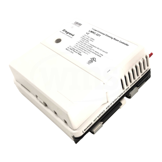
1 Load Universal Dimming Room Controller
1 Load Universal Dimming Room Controller
LMRC-221
LMRC-221
120/277VAC, 50/60Hz
120/277VAC, 50/60Hz
Class 2 output: 250mA
Class 2 output: 250mA
Compatible loads:
Compatible loads:
• 20A @ 120/277V: Incandescent, MLV, ELV and LED
• 20A @ 120/277V: Incandescent, MLV, ELV and LED
• 1920 W @ 120V, 4432 W @ 277V: neon/cc, 2 wire
• 1920 W @ 120V, 4432 W @ 277V: neon/cc, 2 wire
UL 2043 Plenum Rated
UL 2043 Plenum Rated
This unit is pre-set for Plug n' Go™ operation,
adjustment is optional.
For full operational details, adjustment and more features of the
product, see the DLM System Installation Guide provided with
Wattstopper room controllers, and also available at
www.legrand.us/wattstopper.
Installation shall be in accordance with all applicable regulations,
local and NEC codes. Wire connections shall be rated suitable for
the wire size (lead and building wiring) employed.
For Class 2 DLM devices and device wiring: To be connected to a
Class 2 power source only. Do not reclassify and install as Class 1,
or Power and Lighting Wiring.
LMRC-221
Daylighting
Room
Sensor
Controller
CAUTION: TO CONNECT A COMPUTER TO THE DLM LOCAL NETWORK USE THE LMCI-100.
(forward phase compatible)
(forward phase compatible)
and 3 wire electronic fluorescent dimming ballasts
and 3 wire electronic fluorescent dimming ballasts
- 2 wire (Advance® Mark X or =)
- 2 wire (Advance® Mark X or =)
®
- 3 wire (Lutron® Hi-Lume or =)
- 3 wire (Lutron® Hi-Lume or =)
®
Indoor Use Only
75 C Copper Wire Only
75 C Copper Wire Only
Industrial Control
Equipment
46A9
PLACEMENT EXAMPLE
Corner Mount
Occupancy
Sensor
J Box
To
Load
NEVER CONNECT THE DLM LOCAL NETWORK TO AN ETHERNET PORT –
IT MAY DAMAGE COMPUTERS AND OTHER CONNECTED EQUIPMENT.
Wattstopper
DLM 1 Load Universal Dimming Room Controller
Installation Instructions • Instructions d'Installation • Instrucciones de Instalación
Input Voltage ....................................................................120/277VAC, 50/60Hz
Minimum Load Rating ..............................................................................10 watt
Maximum Load Ratings
Incandescent, Quartz Halogen, LED Drivers*
Magnetic Low Voltage* Transformer (MLV) ........................................... 20A
Electronic Low Voltage* Transformer (ELV) .......................................... 20A
Electronic Fluorescent Dimming Ballasts:
2 Wire Advance® Mark X or equal
3 Wire Lutron® Hi-Lume or Eco-10
Neon/Cold Cathode (cc) ............................................ 1920 W @ 120 V
................................................................................... 4432 W @ 277 V
* Forward Phase compatible, dimming rated only
Output to DLM Local Network ........................................ up to 250mA @ 24VDC
Connection to the DLM Local Network ...........................................4 RJ-45 ports
DLM Local Network characteristics when using LMRC-11x/2xx room controllers:
Low voltage power provided over Cat 5e cable (LMRJ);
max current 800mA. Supports up to 64 load addresses,
48 communicating devices including up to 4 LMRC-10x
series and/or LMPL-101 controllers.
Free topology up to 1,000' max.
Environment ........................................................................ For Indoor Use Only
Operating Temperature ........................................32° to 131°F (0° to 55°C)
Storage Temperature ......................................... 23° to 176°F (-5° to 80°C)
Relative Humidity ............................................. 5 to 95% (non condensing)
Max Branch Circuit Overcurrent Protection ................................................... 25A
Patent Pending
DLM Local Network
(low voltage, Class 2)
LMRJ cables
Ceiling Mount
Occupancy
Switch/
Sensor
Dimmer
®
SPECIFICATIONS
WARNING: TURN THE POWER OFF AT
THE CIRCUIT BREAKER BEFORE WIRING.
Advertisement
Table of Contents

Related Manuals for LEGRAND Wattstopper LMRC-221


Summary of Contents for LEGRAND Wattstopper LMRC-221
- Page 1 800mA. Supports up to 64 load addresses, Wattstopper room controllers, and also available at 48 communicating devices including up to 4 LMRC-10x www.legrand.us/wattstopper. series and/or LMPL-101 controllers. Free topology up to 1,000’ max. Installation shall be in accordance with all applicable regulations, Environment ................
- Page 2 MOUNTING THE CONTROLLER LINE VOLTAGE WIRING The room controller mounts to a four square deep junction box using the included mounting plate with the hinge pins extending away from the box as shown. Mounting plate Slide the rubber hinge Tighten mounting screw stopper into the hinge slot using screwdriver.
- Page 3 DIMMING CURVE SELECTION PROCEDURE The Dimming Curve button allows selection of the appropriate curve for the connected load type. By default, the curve is factory set to Curve 1, which is for incandescent, MLV, LED, ELV, and neon/cc loads. Step 1 Load Selection Press and hold the Load button for the load that you wish to configure.
- Page 4 No. 24179 – 03/20 rev.2 © Copyright 2020 Legrand All Rights Reserved. 800.879.8585 © Copyright 2020 Tous droits réservés Legrand. www.legrand.us/wattstopper © Copyright 2020 Legrand Todos los derechos reservados.
Need help?
Do you have a question about the Wattstopper LMRC-221 and is the answer not in the manual?
Questions and answers