Table of Contents
Advertisement
Quick Links
Advertisement
Table of Contents

Related Manuals for Samson RINGO RV D Series


Summary of Contents for Samson RINGO RV D Series
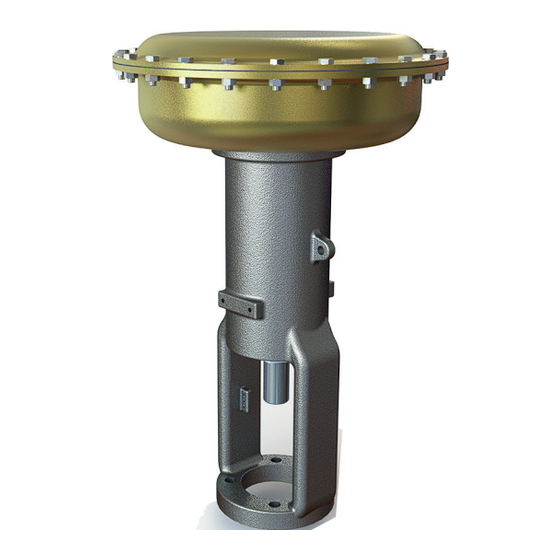
- Page 1 EB 8318 EN Translation of original instructions Type RVXXXD Pneumatic Actuator Type RVXXXR Pneumatic Actuator Pneumatic Actuator 3276 Type RV350D/R, Type RV370D/R, Type RV380D/R, Type RV390D/R Actuator area: 258, 387, 645 and 1032 cm² Edition June 2024...
- Page 2 Note on these mounting and operating instructions These mounting and operating instructions assist you in mounting and operating the device safely. The instructions are binding for handling RINGO devices. The images shown in these instructions are for illustration purposes only. The actual product may vary. Î...
-
Page 3: Table Of Contents
Contents Safety instructions and measures ..............1-1 Notes on possible severe personal injury ............1-3 Notes on possible personal injury ..............1-4 Notes on possible property damage .............1-5 Warnings on the device ................1-7 Markings on the device ................2-1 Actuator nameplate ..................2-1 Design and principle of operation ...............3-1 Direction of action ..................3-1 Fail-safe action ...................3-8 Versions .....................3-8... - Page 4 Contents Servicing....................8-1 Periodic testing ...................8-2 Service work preparations ................8-2 Installing the valve after service work ............8-3 Service work....................8-3 8.3.1 Replacing the diaphragm ................8-3 8.3.2 Replacing the gaskets (Type RVXXXR/fail-close only) ..............8-5 Ordering spare parts and operating supplies ..........8-8 Decommissioning ..................9-1 Removal ....................10-1 10.1 Removing the actuator from the valve ............10-2 10.2...
-
Page 5: Safety Instructions And Measures
Safety instructions and measures 1 Safety instructions and measures Intended use The Types RV350D/R, RV370D/R, RV380D/R and RV390D/R Pneumatic Actuators are de- signed for operating a mounted globe valve. In combination with the valve, the actuators are used to shut off the flow of liquids, gases or vapors in the pipeline. Depending on the ver- sion, the actuators are suitable for throttling or on/off service. - Page 6 Safety instructions and measures Explosion-protected versions of this device must be operated only by personnel who has un- dergone special training or instructions or who is authorized to work on explosion-protected devices in hazardous areas. Personal protective equipment RINGO recommends wearing the following personal protective equipment when handling the pneumatic actuator: −...
-
Page 7: Notes On Possible Severe Personal Injury
Safety instructions and measures Responsibilities of the operator Operators are responsible for proper use and compliance with the safety regulations. Opera- tors are obliged to provide these mounting and operating instructions as well as the refer- enced documents to the operating personnel and to instruct them in proper operation. Fur- thermore, operators must ensure that operating personnel or third parties are not exposed to any danger. -
Page 8: Notes On Possible Personal Injury
Safety instructions and measures 1.2 Notes on possible personal injury WARNING Crush hazard arising from moving parts. The actuator contains moving parts (actuator stem), which can injure hands or fingers if inserted into the actuator. Î Do not touch the actuator stem or insert hands or finger into the yoke or beneath the actuator stem while the air supply is connected to the actuator. -
Page 9: Notes On Possible Property Damage
Safety instructions and measures WARNING Exposure to hazardous substances poses a serious risk to health. Certain lubricants and cleaning agents are classified as hazardous substances. These substances have a special label and a material safety data sheet (MSDS) issued by the manufacturer. - Page 10 Safety instructions and measures NOTICE Risk of actuator damage due to the use of unsuitable lubricants. The lubricants to be used depend on the actuator material. Unsuitable lubricants may corrode and damage surfaces. Î Only use lubricants approved by RINGO. EB 8318 EN...
-
Page 11: Warnings On The Device
Safety instructions and measures 1.4 Warnings on the device Warning symbols Meaning of the warning Location on the device Warning against the incorrect use of the lifting eyelet/eyebolt or swivel hoist on the actuator. Only attach load-bearing slings to them to vertically lift the actuator on its own (without the valve). - Page 12 EB 8318 EN...
-
Page 13: Markings On The Device
Markings on the device 2 Markings on the device Permissible supply pressure p in psi Permissible supply pressure p in bar The nameplate shown was up to date at the Operating travel in mm time of publication of this document. The nameplate on the device may differ from the Manufacturer specifications one shown. - Page 14 EB 8318 EN...
-
Page 15: Design And Principle Of Operation
Design and principle of operation 3 Design and principle of oper- the signal pressure connection on the top diaphragm case (850) of the actuator. ation − Version R (reverse-acting, actuator stem See Fig. 3-1 to Fig. 3-5 extends) The Types RV350D/R, RV370D/R, With fail-safe action "actuator stem ex- RV380D/R and RV390D/R Pneumatic Actu- tends", the compressed air is applied to ators are mounted to Series 590 Valves... - Page 16 Design and principle of operation Fig. 3-1: Type RVXXXD Actuator · Fail-open (actuator stem retracts) Legend for Fig. 3-1 and Fig. 3-2 Screw (to fasten dia- Diaphragm stud Housing with yoke phragm base and cover) (top-mounted handwheel) Actuator stem Screw (bottom diaphragm 1030 Housing nut (top-mounted Spring case) handwheel)
- Page 17 Design and principle of operation 1030 1031 1034 Fig. 3-2: Type RVXXXD Actuator with top-mounted handwheel (actuator stem retracts) EB 8318 EN...
- Page 18 Design and principle of operation Fig. 3-3: Type RVXXXD Actuator with side-mounted handwheel (actuator stem retracts) EB 8318 EN...
- Page 19 Design and principle of operation Legend Housing with yoke 600 Handwheel 940 Handwheel housing 941 Drive (handwheel) 942 Drive nut 947 Bearing bushing (handwheel) 948 Lever arm 949 Drive pin (lever arm) 952 Pivot pin (lever arm) 955 Clamping bolt 956 Screw 957 Bushing for pivot pin (lever arm) 960 Bearing...
- Page 20 Design and principle of operation Fig. 3-4: Type RVXXXR Actuator (actuator stem extends) Legend for Fig. 3-4 and Fig. 3-5 Housing with yoke Yoke flange Seal (bottom diaphragm case) Actuator stem Spring adjuster Travel indicator Adjustment screw Stem connector Handwheel housing Washer Actuator diaphragm Drive (handwheel) Spring Screw (bottom diaphragm...
- Page 21 Design and principle of operation 1030 1027 1029 Fig. 3-5: Type RVXXXR Actuator with top-mounted handwheel (actuator stem extends) EB 8318 EN...
-
Page 22: Fail-Safe Action
Type RV380… and Type RV390… Pneumat- The listed fail-safe actions apply to ic Actuators are available in the version D or SAMSON Series 590 Valves (globe valves). R with 258, 387, 645 or 1032 cm² actuator areas. When the signal pressure is reduced or the... - Page 23 Design and principle of operation EB 8318 EN...
-
Page 24: Technical Data
Design and principle of operation 3.5 Technical data The nameplate provides information on the actuator version (see the 'Markings on the device' chapter). Note More information is available in Data Sheet u T 8318. Table 3-1: Technical data Type RV350…, Type RV370…, Version D Version R Type RV380…, Type RV390…... - Page 25 Design and principle of operation Table 3-3: Maximum effective thrusts in N Actuator Bench Travel (mm) Version area range (cm²) (bar) 0.2 to 1 11594 – – – – 1) 0.4 to 2 8918 – – – – 1) 0.2 to 1 17390 –...
- Page 26 Design and principle of operation Table 3-4: See Fig. 3-6 and Fig. 3-8 for dimensions and weights of Type RVXXXD Version Type RV… 320D 330D 350D 350D 380D 390D Actuator area [cm²] 1032 Travel (mm) Without handwheel Handwheel (top) With side-mounted hand- wheel ¼ ¼...
- Page 27 Design and principle of operation Ø D Ø D Ø D Type RVXXXD without hand- Type RVXXXD with top-mounted Type RVXXXD with side-mounted wheel handwheel handwheel Fig. 3-6: Dimensional drawings for Type RVXXXD EB 8318 EN 3-13...
- Page 28 Design and principle of operation Table 3-5: See Fig. 3-7 and Fig. 3-8 for dimensions and weights of Type RVXXXR Version Type RV… 320R 330R 350R 350R 380R 390R Actuator area [cm²] 1032 Travel (mm) Without handwheel Handwheel (top) With side-mounted hand- wheel ¼ ¼...
- Page 29 Design and principle of operation Ø D Ø D Ø D Type RVXXXR without Type RVXXXR with top- Type RVXXXR with side-mounted handwheel mounted handwheel handwheel Fig. 3-7: Dimensional drawings for Type RVXXXR EB 8318 EN 3-15...
- Page 30 Design and principle of operation Actuator stem retracted Ø D Ø D Ø D Ø D N x Screw Fig. 3-8: Dimensional drawing of housing connections 3-16 EB 8318 EN...
-
Page 31: Shipment And On-Site Transport
Shipment and on-site transport 4 Shipment and on-site trans- Î Leave the actuator in its transport con- tainer or on the pallet to transport it on port site. The work described in this chapter is to be Î Dispose and recycle the packaging in ac- performed only by personnel appropriately cordance with the local regulations. -
Page 32: Transporting The Actuator
Shipment and on-site transport − Protect the actuator against moisture and NOTICE dirt. Risk of actuator damage due to incorrectly − Observe permissible temperatures (see attached slings. section 'Technical data' in the 'Design Only use the lifting eyelets/eyebolts or swivel and principle of operation' chapter). - Page 33 Shipment and on-site transport 2. Attach the sling to these lifting eyelets ging equipment (hook, shackle etc.) must not and to the rigging equipment (e.g. hook) bear any load. The slings only protect the of the crane or forklift. control valve from tilting while being lifted. Before lifting the control valve, tighten the 3.
-
Page 34: Storing The Actuator
Shipment and on-site transport Storage instructions − When the valve and actuator are al- ready assembled, observe the storage conditions for control valves. See associ- ated valve documentation. − Protect the actuator against external in- fluences (e.g. impact). − Secure the actuator in the stored position against slipping or tipping over. - Page 35 Shipment and on-site transport Our after-sales service can provide more de- tailed storage instructions on request. EB 8318 EN...
- Page 36 EB 8318 EN...
-
Page 37: Installation
(e.g. due to operation' section seizing up after remaining in the same Depending on the version, SAMSON control position for a long time), release any valves are either delivered with the actuator stored energy in the actuator (e.g. spring compression). -
Page 38: Pneumatic Connection
Installation b) Version R, fail-close (actuator spring compression in the actuator' in the 'Removal' chapter. stem extends) 1. Apply a signal pressure that corresponds NOTICE to the lower signal pressure range value Risk of actuator damage due to over- or to the connection on the bottom dia- under-torquing. -
Page 39: Mounting The Actuator Onto The Valve
Installation Determine the lower and upper signal pres- NOTICE sure range values Risk of actuator damage due to excessively 1. Turn the spring adjuster (906) clockwise high supply pressure. until loading of the actuator spring (595) Î Do not allow the supply pressure to ex- starts. - Page 40 Installation 2. Thread the lock nut and travel indicator 4. Fasten the valve bonnet and actuator (921) downward on the plug stem of the yoke together. Observe tightening valve. torques. 3. Place the actuator with the yoke first ver- 5. Connect the signal pressure (see Chap- tically onto the valve bonnet while align- ter 5.2.1).
-
Page 41: Operation
Operation 6 Operation WARNING The work described in this chapter is to be Risk of personal injury due to incorrect op- performed only by personnel appropriately eration, use or installation as a result of in- qualified to carry out such tasks. correct information on the actuator. -
Page 42: Neutral Position Of Top-Mounted Handwheel
Operation 6.2.1 Neutral position of top- mounted handwheel Version D The handwheel is in the neutral position when it is turned to the top position (see Fig. 3-2 in the 'Design and principle of oper- ation' chapter). Version R The handwheel is in the neutral position when it is turned to the lowest position (see Fig. 3-5 in the 'Design and principle of oper- ation' chapter). -
Page 43: Malfunctions
Malfunctions 7 Malfunctions Read hazard statements, warnings and caution notes in the 'Safety instructions and mea- sures' chapter. 7.1 Troubleshooting Malfunction Possible reasons Recommended action Actuator stem does not Actuator is blocked. Put the control valve out of operation (see the move on demand. -
Page 44: Emergency Action
Malfunctions 7.2 Emergency action Plant operators are responsible for emergen- cy action to be taken in the plant. EB 8318 EN... -
Page 45: Servicing
Servicing 8 Servicing WARNING WARNING The work described in this chapter is to be Crush hazard arising from the moving actu- performed only by personnel appropriately ator stem. qualified to carry out such tasks. Î Do not insert hands or finger into the yoke while the air supply is connected to the actuator. -
Page 46: Periodic Testing
Servicing 8.1 Periodic testing NOTICE Risk of actuator damage due to over- or Depending on the operating conditions, under-torquing. check the actuator at certain intervals to pre- Observe the specified torques when tighten- vent possible failure before it can occur. ing actuator components. -
Page 47: Installing The Valve After Service Work
Servicing 8.2 Installing the valve after 5. Unscrew the screw (914) from the actua- tor stem (61). service work 6. Remove silicone and take the diaphragm Î Mount the actuator onto the valve (see holder (902), diaphragm (911) and dia- the 'Installation' chapter). - Page 48 Servicing b) Type RVXXXR, fail-close (ac- 11. Mount the bushing (903) including the O-rings (924, 925) and the retaining tuator stem extends) ring (918). 12. Place the parts on the actuator stem in Version without handwheel and version the specified order: with side-mounted handwheel −...
-
Page 49: Replacing The Gaskets (Type Rvxxxr/Fail-Close Only)
Servicing 6. Lift off the top diaphragm case (850). − Diaphragm plate (901) 7. Pull the diaphragm plate assembly con- 17. Use the screw (914) to fasten the parts sisting of the diaphragm plate (901), onto the actuator stem (61). Observe screw (914), actuator stem (61), dia- tightening torque. - Page 50 Servicing phragm (911) and diaphragm holder 14. Unscrew the screw (914) from the actua- (902) into the top position. tor stem (61). 4. Remove the retaining ring (918) and 15. Take the diaphragm plate (901), dia- then the bushing (903) including the phragm (911) and diaphragm holder O-rings (924, 925).
- Page 51 Servicing − It guides the spring (595) and actuator 10. Firmly clamp the actuator stem (61) in stem (61) in the actuator housing (40). the area above the thread for the spring − It loads the spring (see 'Setting the actua- adjuster into a vise using protective jaws.
-
Page 52: Ordering Spare Parts And Operating Supplies
21. Insert the actuator stem (61) into the bot- tom diaphragm case (900). operating supplies 22. Renew O-rings (924, 925). Contact your nearest SAMSON subsidiary 23. Mount the bushing (903) including the or RINGO's after-sales service for informa- new O-rings (924, 925) and the retain- tion on spare parts, lubricants and tools. -
Page 53: Decommissioning
Decommissioning 9 Decommissioning WARNING WARNING The work described in this chapter is to be Crush hazard arising from the moving actu- performed only by personnel appropriately ator stem. qualified to carry out such tasks. Î Do not insert hands or finger into the yoke while the air supply is connected to the actuator. - Page 54 EB 8318 EN...
-
Page 55: Removal
Removal 10 Removal WARNING WARNING The work described in this chapter is to be Crush hazard arising from the moving actu- performed only by personnel appropriately ator stem. qualified to carry out such tasks. Î Do not touch the actuator stem or insert hands or finger into the yoke while the air supply is connected to the actuator. -
Page 56: Removing The Actuator From The Valve
Removal 10.1 Removing the actuator 1. Unscrew the two screws (915) opposite each other on the bottom diaphragm from the valve case (900) and replace them with longer See images in the 'Design and principle of screws, which stick out of the actuator operation' section housing (40) by approx. -
Page 57: Repairs
Repairs 11 Repairs The declaration form can be downloaded from our website at u .www.samsongroup. If the actuator does not function properly ac- com > Service > After-sales Service > cording to how it was originally sized or Returning goods does not function at all, it is defective and must be repaired or exchanged. - Page 58 11-2 EB 8318 EN...
-
Page 59: Disposal
Disposal 12 Disposal Î Observe local, national and internation- al refuse regulations. Î Do not dispose of components, lubricants and hazardous substances together with your household waste. EB 8318 EN 12-1... - Page 60 12-2 EB 8318 EN...
-
Page 61: Appendix
Appendix 13 Appendix 13.1 Tightening torques, lubricants and tools Tightening torques Table 13-1: Type RV330D Tightening torque in Nm Target value (max. value) With With Without top-mounted side-mounted handwheel handwheel handwheel 49.31 Threaded pin GR 8.8 (98.61) 30.23 Stem connector screw GR 8.8 – (60.46) Screw (to fasten 49.31... - Page 62 Appendix Tightening torque in Nm Target value (max. value) With With Without top-mounted side-mounted handwheel handwheel handwheel 30.23 Stem connector screw GR 8.8 – (60.46) 14.02 1951 Ring bolt GR 18.8 (18.23) Table 13-2: Type RV350D Tightening torque in Nm Target value (max. value) With With Without top-mounted...
- Page 63 Appendix Tightening torque in Nm Target value (max. value) With With Without top-mounted side-mounted handwheel handwheel handwheel Housing bolt (side- 14.50 GR 8.8 – mounted handwheel) (28.99) 49.31 Diaphragm stud GR 8.8 – – (98.61) 14.50 Stem connector screw GR 8.8 – (28.99) 29.24 1951 Ring bolt GR 18.8...
- Page 64 Appendix Tightening torque in Nm Target value (max. value) With With Without top-mounted side-mounted handwheel handwheel handwheel Threaded pin 6.06 GR 8.8 – (handwheel housing) (12.13) 49.31 Spacer bolt (lever arm) GR 8.8 – (98.61) Housing bolt (side- 14.50 GR 8.8 – mounted handwheel) (28.99) 49.31 Diaphragm stud...
- Page 65 Appendix Tightening torque in Nm Target value (max. value) With With Without top-mounted side-mounted handwheel handwheel handwheel 15.90 Screw F-112 – (31.80) 49.31 Stop bolt GR 8.8 – (98.61) Threaded pin 6.06 GR 8.8 – (handwheel housing) (12.13) 49.31 Spacer bolt (lever arm) GR 8.8 –...
- Page 66 Appendix Table 13-5: Type RV330R Tightening torque in Nm Target value (max. value) With With Without top-mounted side-mounted handwheel handwheel handwheel 49.31 Threaded pin GR 8.8 (98.61) 30.23 Stem connector screw GR 8.8 – (60.46) 49.31 – Screw (to fasten GR 8.8 (98.61) diaphragm base and –...
- Page 67 Appendix Tightening torque in Nm Target value (max. value) With With Without top-mounted side-mounted handwheel handwheel handwheel 14.02 GR 18.8 – (18.23) 1951 Ring bolt 14.50 GR 8.8 – (18.84) Table 13-6: Type RV350R Tightening torque in Nm Target value (max. value) With With Without top-mounted side-mounted handwheel...
- Page 68 Appendix Tightening torque in Nm Target value (max. value) With With Without top-mounted side-mounted handwheel handwheel handwheel Housing bolt (side- 14.50 GR 8.8 – mounted handwheel) (28.99) 49.31 Diaphragm stud GR 8.8 – – (98.61) 14.50 Stem connector screw GR 8.8 – (28.99) 49.31 1029 Bolt (housing) GR 8.8...
- Page 69 Appendix Tightening torque in Nm Target value (max. value) With With Without top-mounted side-mounted handwheel handwheel handwheel 49.31 Stop bolt GR 8.8 – (98.61) Threaded pin 6.06 GR 8.8 – (handwheel housing) (12.13) 49.31 Spacer bolt (lever arm) GR 8.8 – (98.61) Housing bolt (side- 231.59 GR 8.8 –...
- Page 70 Appendix Tightening torque in Nm Target value (max. value) With With Without top-mounted side-mounted handwheel handwheel handwheel A479 Pin (threaded bushing) – T410 (78) 152.14 Clamping bolt F-114 " – (304.27) 15.90 Screw F-112 – (31.80) 49.31 Stop bolt GR 8.8 – (98.61) Threaded pin 6.06...
-
Page 71: Spare Parts
Appendix 13.2 Spare parts Retaining ring (bushing) Travel indicator nut Housing with yoke Screw (travel indicator) Actuator stem Travel indicator Adjustment screw Vent plug Threaded pin O-ring (bottom diaphragm case) Key drive Internal O-ring (bushing) Washer External O-ring (bushing) Spring Seal (bottom diaphragm case) Handwheel Travel indicator scale... - Page 72 Appendix 2250 Washer (bottom diaphragm case) Washer Threaded pin (handwheel housing) Spacer bolt (lever arm) Spacer nut (lever arm) Spacer washer (lever arm) Ball Spring Housing bolt (side-mounted handwheel) Housing washer (side-mounted hand- wheel) Diaphragm stud (top-mounted hand- wheel) 1007 Spacer (yoke) 1027 Anti-rotation fixture...
- Page 73 Appendix Type RVXXXD Actuator 1330 1331 1034 1032 1033 EB 8318 EN 13-13...
- Page 74 Appendix Version with side-mounted handwheel 941 949 13-14 EB 8318 EN...
- Page 75 Appendix Type RVXXX-R Actuator 1030 1031 1027 1029 EB 8318 EN 13-15...
-
Page 76: After-Sales Service
Calle Romero Nº6 Polígono Industrial Empresarium 50720 Zaragoza · Spain Addresses of SAMSON AG and its subsid- iaries The addresses of SAMSON AG, its subsid- iaries, representatives and service facilities worldwide can be found on our website (www.samsongroup.com) or in all SAMSON product catalogs. - Page 80 EB 8318 EN RINGO VÁLVULAS S.L. Calle Romero Nº6 Polígono Industrial Empresarium 50720 Zaragoza · Spain Phone: +34 976 45 49 40 · email: info-ringo-es@samsongroup.com Internet: www.ringospain.com...
Need help?
Do you have a question about the RINGO RV D Series and is the answer not in the manual?
Questions and answers