Samson 3372 Mounting And Operating Instructions
Electropneumatic actuator versions with 120 and 350 cm and type 3725 positioner
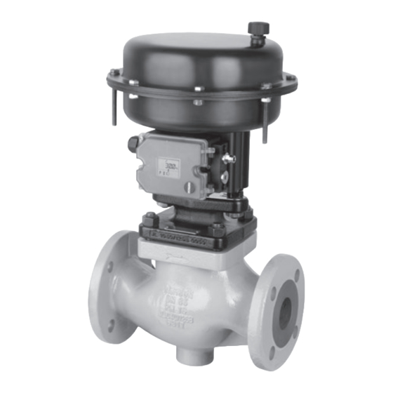
eb 8313-3 en
Hide thumbs
Also See for 3372:
- Mounting and operating instructions (80 pages) ,
- User manual (8 pages) ,
- Mounting and operating instructions (60 pages)
Table of Contents
Advertisement
Advertisement
Table of Contents

Related Manuals for Samson 3372


Summary of Contents for Samson 3372
- Page 1 Type 3372 Electropneumatic Actuator Versions with 120 and 350 cm² and Type 3725 Positioner Globe valve with Type 3372 Electropneumatic Actuator Versions with 120 cm² and 350 cm² effective diaphragm areas Mounting and Operating Instructions EB 8313-3 EN Edition July 2013...
- Page 2 Definition of signal words DANGER! NOTICE Hazardous situations which, if not Property damage message or mal- avoided, will result in death or seri- function ous injury Note: WARNING! Additional information Hazardous situations which, if not avoided, could result in death or seri- Tip: ous injury Recommended action...
-
Page 3: Table Of Contents
Type 3372 (120 cm²) ...................16 4.1.1 Mounting using a central nut .................16 4.1.2 Mounting using rods ..................18 Type 3372 (350 cm²) – mounting using rods ..........18 Changing the type of mounting ..............20 4.3.1 Conversion of mounting using a central nut to rods .........20 4.3.2 Conversion of mounting using rods to a central nut .........20... - Page 4 Contents Maintenance of Type 3372 (120 cm²) ............28 Removing the actuator ..................28 6.1.1 Releasing the spring preloading ..............28 Removing the diaphragm plate assembly ............28 Dismantling the diaphragm plate assembly ............30 6.3.1 Version with fail-safe action „actuator stem extends“ (FA) ........30 6.3.2...
-
Page 5: Eb 8313-3 En
Contents Nameplate ....................40 Dimensions and weights ................40 Customer inquiries ..................41 EB 8313-3 EN... -
Page 7: General Safety Instructions
General safety instructions 1 General safety instructions − The actuator is to be mounted, started up or operated only by trained and experienced personnel familiar with the product. According to these mounting and operating instruc- tions, trained personnel refers to individuals who are able to judge the work they are as- signed to and recognize possible dangers due to their specialized training, their knowl- edge and experience as well as their knowledge of the applicable standards. -
Page 8: Design And Principle Of Operation
Design and principle of operation 2 Design and principle of oper- 2.1 Versions ation 2.1.1 Type 3372 (120 cm²) The Type 3372 Electropneumatic Actuator is mainly used for attachment to Series V2001 − Actuator with die-cast aluminum housing Valves: − Standard use for attachment to −... - Page 9 Design and principle of operation Diaphragm case Compressor Diaphragm Diaphragm plate Radial shaft seal Actuator stem Wiper ring Compression spring Plain bearing Collar nut Hexagon nut (for 33) Hexagon bolt Plate Hexagon nut Support element Washer Fig. 1: Type 3372 Actuator (350 cm²) EB 8313-3 EN...
- Page 10 Design and principle of operation Table 1: Attachment of Type 3372 Actuator to Series V2001 Valves 120 cm² Stem extends Stem retracts 2.1 to 3.3 1.4 to 2.3 0.4 to 1.4 1.4 to 2.3 Type Travel 15 mm 3321 15 to 50 0.25 to 35...
- Page 11 Design and principle of operation 350 cm² Stem Stem Stem Stem extends retracts extends retracts 2.1 to 2.7 1.5 to 2.1 2.2 to 3.8 1.5 to 2.7 15 mm 30 mm Type – – – – 0.25 to 35 15 to 50 3321 –...
-
Page 12: Signal Pressure Routing
Design and principle of operation Table 2: Mounting on Type 3372 Actuator on HVAC volves Version Type 3725 Positioner (direct attachment) Actuator area 120 cm² Travel 15 mm 30 mm Type to Valve Nominal size DN 3214 65 to 100 Form B – 3214 125 to 150 –... -
Page 13: Fail-Safe Action
Note It is not possible to change the oper- ating direction of Type 3372 Actua- tor by changing the location of the diaphragm plate. 2.3.1 Version with fail-safe action “actuator stem extends“... -
Page 14: Technical Data
Application 2.4 Technical data Type 3372 Actuator Diaphragm area 120 cm² 350 cm² Bench range in bar 0.4 to 2.1 to 1.5 to 2.1 to 1.5 to 2.2 to 1.4 to 2.3 Fail-safe action Stem Stem Stem Stem Stem Stem... -
Page 15: Throttling Service
Application 3.1 Throttling service The Type 3372 Pneumatic Actuator is de- signed for a maximum supply pressure of 6 bar when used for throttling service. 3.2 On/off service To prevent the actuator from being dam- aged, the supply pressure must not exceed the upper spring range value by more than 3 bar at the maximum when the actuator with fail-safe action „actuator stem retracts“... -
Page 16: Mounting On The Valve
This causes the actuator stem to be pressed down approximately 1 to 2 mm 4.1 Type 3372 (120 cm²) against the force of the springs. Tightening torque of the nut = 150 Nm. The actuator is normally mounted onto the... - Page 17 Mounting on the valve Valve bonnet Central nut Hex nut (for 33) Crossbeam Fig. 4: Mounting using central nut – Type 3372-120 cm² EB 8313-3 EN...
-
Page 18: Mounting Using Rods
4.1.2 Mounting using rods 4.2 Type 3372 (350 cm²) – mounting using rods See Table 1 on page 10 for Form C The Type 3372 Actuator (120 cm²) is suit- See Table 1 on page 10 for Form C able for mounting on Type 3321 Valves in Fig. 5 DN 65 to 100 with 15 mm travel. - Page 19 Mounting on the valve Valve bonnet Hex nut (for 33) Plate Fig. 5: Mounting on rods - Type 3372 (350 cm²) EB 8313-3 EN...
-
Page 20: Changing The Type Of Mounting
Î Place the rods (33) on the valve bonnet (34) and tighten both hex nuts (54) alter- mounting nately. A Type 3372 Actuator (120 cm²) which has Î Mount the stem connector between the already been mounted using a central nut actuator stem and plug stem, ensuring... - Page 21 Mounting on the valve Valve bonnet Central nut Hex nut (for 33) Crossbeam Fig. 6: Mounting using central nut – Type 3372 (120 cm²) 33.1 33.1 Adapter bushing Valve bonnet Hex nut (for 33) Plate Fig. 7: Mounting on rods - Type 3372-120 cm² EB 8313-3 EN...
-
Page 22: Attaching The Type 3725 Positioner
Mounting on the valve 4.4 Attaching the Type 3725 4.4.1 Actuator with fail-safe Positioner action „actuator stem extends“ (FA) Fig. 8 If the positioner (62) is to be used with an The signal pressure is routed from the posi- actuator with fail-safe action „actuator stem tioner (62) through a hole in the support ele- extends“... - Page 23 Mounting on the valve 62.1 62.2 Support element Type 3725 Positioner 62.1 Follower pin 62.2 Lever Fig. 8: Attaching the Type 3725 Positioner EB 8313-3 EN...
-
Page 24: Attaching The Type 4744-2 Limit Switch
Î Position the clamping plate on the rod (33) at the point where the lever rests on the bracket of the stem connector. Fig. 9: Type 4744-2 Limit Switch attached to Type 3323/3372 Control Valve EB 8313-3 EN... -
Page 25: Operation
It is essential that the vent plug lets air Fig. 10: Travel limit in actuators (120 cm²) through it to allow the actuator to work properly. 5.1.1 Limiting the minimum 5.1 Type 3372 (120 cm²) with travel travel stop Î Undo lock nut (101) and remove cover (100). Fig. 10 Î... -
Page 26: Limiting The Maximum Travel
The actuator stem ex- reaches the stop point and retighten the tends out of the actuator. lock nut (101). 5.2 Type 3372 (120 cm²) with manual override Fig. 11 The actuator stem can be moved by the op- tional manual override over a shaft (72). The actuator is moved opposing the force of its springs. - Page 27 Operation Radial shaft seal Shaft Cover Sleeve Washer Fig. 11: Manual override for Type 3372 (120 cm²) EB 8313-3 EN...
-
Page 28: Maintenance Of Type 3372 (120 Cm²)
Maintenance of Type 3372 (120 cm²) 6 Maintenance of Type 3372 applies for an actuator fitted with manual override. (120 cm²) Mark both diaphragm cases (1 and 2) to en- Fig. 12 sure that the pneumatic connections are If the actuator does function properly, it may mounted correctly later on reassembling the be necessary to replace parts subject to wear actuator. - Page 29 Maintenance of Type 3372 (120 cm²) Version with fail-safe action: "stem retracts" Version with fail-safe action: "stem extends" Diaphragm case Collar nut Diaphragm Hex nut Diaphragm plate Radial shaft seal Diaphragm plate Wiper ring (small) Plain bearing Actuator stem Compression spring Fig. 12: 120 cm²...
-
Page 30: Dismantling The Diaphragm Plate Assembly
Maintenance of Type 3372 (120 cm²) 6.3 Dismantling the diaphragm Assemble in the reverse order as described for dismantling. The parts are to be assem- plate assembly bled as shown in the associated drawing. The diaphragm plate assembly only needs to 6.4.1... -
Page 31: Radial Shaft Seal, Wiper Ring And Plain Bearings
Maintenance of Type 3372 (120 cm²) 6.5.1 Radial shaft seal, wiper Î Install the new radial shaft seal, making sure the seal lip does not get damaged. ring and plain bearings Before assembling, check each part, espe- Î Use a suitable mandrel or hook to re- cially the diaphragm, for damage. -
Page 32: Version With Manual Override
Fig. 14 Î Use a suitable piece of pipe to install a The Type 3372 Actuator (120 cm²) can op- new dry bearing. tionally fitted with a manual override. Addi- Î Install the new radial shaft seal, making tionally, a radial shaft seal and a dry bear- sure the seal lip does not get damaged. -
Page 33: Mounting The Actuator
Maintenance of Type 3372 (120 cm²) 6.6 Mounting the actuator 6.6.2 Version with fail-safe action „actuator stem Fig. 15 retracts“ (FE) 6.6.1 Version with fail-safe Î Clamp the top diaphragm case (1) into a action „actuator stem suitable appliance. This ensures that the extends“... -
Page 34: Mounting On The Valve
Maintenance of Type 3372 (120 cm²) Î If the springs are to be preloaded, insert Î Insert the short bolts (20) with nuts (21) the long bolts (20) through the holes and washers. used previously on the top diaphragm Î Tighten all nuts with 6.3 Nm in a criss- case. - Page 35 Maintenance of Type 3372 (120 cm²) Version with fail-safe action: "stem retracts" Version with fail-safe action: "stem extends" 1/2 Diaphragm case Diaphragm plate Compression Radial shaft seal (small) spring Diaphragm Wiper ring Actuator stem Collar nut Plain bearing Diaphragm plate Hex nut Fig. 15: 120 cm²...
-
Page 36: Maintenance Of Type 3372 (350 Cm²)
Maintenance of Type 3372 (350 cm²) 7 Maintenance of Type 3372 7.1 Removing the actuator (350 cm²) The actuator must be dismantled to replace, for example, damaged seals or plain bear- Fig. 16 ings. A defective diaphragm additionally re- Parts subject to wear may need to be re-... - Page 37 Maintenance of Type 3372 (350 cm²) Version with fail-safe action: "stem retracts" Version with fail-safe action: "stem extends" Diaphragm case Washer Compressor Diaphragm Diaphragm plate Radial shaft seal Actuator stem Wiper ring Compression spring Plain bearing Collar nut Hex nut (for 33) Hexagon screw...
-
Page 38: Dismantling The Diaphragm Plate Assembly
Maintenance of Type 3372 (350 cm²) 7.3 Dismantling the diaphragm 7.4 Assembly based on the di- plate assembly rection of action The diaphragm plate assembly only needs to Before assembling, check each part, espe- be dismantled if the diaphragm is damaged cially the diaphragm, for damage. -
Page 39: Replacing Seals And Plain Bearing
Î If necessary, remove the wiper ring (41) and plain bearing (42) with a suitable The reversal direction of action, i.e. fail-safe mandrel or piece of pipe. Renew these action, of Type 3372 (120 cm²) and components, if necessary. Type 3372 (350 cm²) Actuators is not in- Î Apply lubricant (8152-0043) to parts tended. -
Page 40: Nameplate
− Configuration ID (Var.-ID) as bar code and plain text − Serial number − Country of origin Actuator stem extends/retracts Type 3372 (120 cm²) with Type 3725, 7 kg − Diaphragm area in cm² (120 cm²/350 cm²) − Symbol for manual override Ø280 − Symbol indicating fail-safe action: FA ·... -
Page 41: Customer Inquiries
Please submit the following details written on the nameplate: − Type designation and serial number − Effective area in cm² − Bench range (spring range) in bar − Actuator version and fail-safe action − Your e-mail address Please send your inquiries to: service@samson.de EB 8313-3 EN... - Page 42 EB 8313-3 EN...
- Page 43 EB 8313-3 EN...
- Page 44 SAMSON AG · MESS- UND REGELTECHNIK Weismüllerstraße 3 · 60314 Frankfurt am Main, Germany Phone: +49 69 4009-0 · Fax: +49 69 4009-1507 EB 8313-3 EN samson@samson.de · www.samson.de...
Need help?
Do you have a question about the 3372 and is the answer not in the manual?
Questions and answers