Samson 3767 Mounting And Operating Instructions
Electropneumatic positioner
Hide thumbs
Also See for 3767:
- Mounting and operating instructions (56 pages) ,
- Translation of original instructions (112 pages)

Related Manuals for Samson 3767


Summary of Contents for Samson 3767
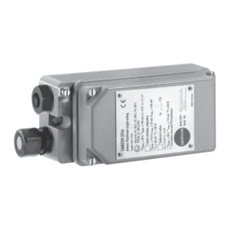
- Page 1 Type 3767 Electropneumatic Positioner Fig. 1: Type 3767 Mounting and Operating Instructions EB 8355-2 EN Edition December 2016...
- Page 2 Definition of signal words DANGER! NOTICE Hazardous situations which, if not Property damage message or mal- avoided, will result in death or seri- function ous injury Note: WARNING! Additional information Hazardous situations which, if not avoided, could result in death or seri- Tip: ous injury Recommended action...
-
Page 3: Table Of Contents
Contents General safety instructions ................5 Design and principle of operation ..............6 Versions and article code ................9 Technical data .....................10 Additional equipment ...................11 Summary of explosion protection approvals ...........12 Mounting on control valves ................14 3.1 Direct attachment to Type 3277 Actuator ............14 3.2 Attachment according to IEC 60534-6 ............21 3.2.1 Mounting sequence ..................22 3.2.2 Initial adjustment of travel ................22 Attachment to rotary actuators ..............25 3.3.1 Mounting the lever with feeler roll ..............26... - Page 4 Contents Converting and retrofitting the positioner .............47 6.1 Converting from electropneumatic to pneumatic ..........47 6.2 Installing the limit contacts ................48 6.3 Installing a solenoid valve ................48 6.4 Removing the solenoid valve .................49 Servicing explosion-protected devices ............49 Dimensions in mm ..................50 4 EB 8355-2 EN...
-
Page 5: General Safety Instructions
General safety instructions 1 General safety instructions For your own safety, follow these instructions concerning the mounting, start up and opera- tion of the device: − The device is to be mounted, started up or operated only by trained and experienced personnel familiar with the product. According to these mounting and operating instruc- tions, trained personnel refers to individuals who are able to judge the work they are as- signed to and recognize possible dangers due to their specialized training, their knowl- edge and experience as well as their knowledge of the applicable standards. − Any hazards that could be caused in the valve by the process medium, the signal pres- sure or by moving parts are to be prevented by taking appropriate precautions. -
Page 6: Design And Principle Of Operation
The air controlled by the booster (signal pres- with nozzle, diaphragm lever (flapper plate), sure p ) flows through the volume restriction and booster. (11) to the pneumatic actuator, causing the The positioner is designed either for direct plug stem to move to a position correspond- attachment to SAMSON Type 3277 Actuators ing to the reference variable. or for attachment to actuators according to The adjustable X restriction (8) and volume NAMUR (IEC 60534-6) using an adapter restriction (11) are used to optimize the posi- housing. tioner control loop. - Page 7 Design and principle of operation Travel Lever 6.2 Zero adjuster Supply 1.1 Pin Turnboard 1.2 Clamp restriction 2.1 Nozzle >> Pressure regulator 2.2 Nozzle <> Booster Diaphragm lever Volume restriction Range spring Solenoid valve Measuring (option) diaphragm i/p converter 6.1 Span adjuster 8 9 10 Fig. 2: Functional diagram and inside view EB 8355-2 EN...
- Page 8 Design and principle of operation When a control signal corresponding to the binary signal '1' (ON) is applied to the in- put, the signal pressure p is applied to the actuator, allowing the valve to move accord- ing to the input signal issued by the control equipment. Positioner with position transmitter A positioner containing a position transmit- ter cannot be equipped with integrated limit contacts or an integrated solenoid valve since the position transmitter requires most of the space inside.
-
Page 9: Versions And Article Code
Design and principle of operation 2.1 Versions and article code Electropneumatic positioner Type 3767- x Explosion protection Without II 2G Ex ia IIC T6 according to ATEX CSA/FM intrinsically safe/non incendive II 3G Ex nA II T6 acc. to ATEX Additional equipment Without Inductive limit contacts 2x SJ2-SN (Analog position transmitter 4 to 20 mA) 3/2-way solenoid valve Without 6 V DC 12 V DC 24 V DC Type of mounting Standard range spring Pneumatic connections ¼-18 NPT ISO 221/1-G ¼ Electrical connections Plastic cable gland M20 x 1.5, blue Plastic cable gland M20 x 1.5, black Cable gland M20 x 1.5, nickel-plated brass... -
Page 10: Technical Data
Design and principle of operation 2.2 Technical data Positioner Travel range, adjustable Direct attachment: 7.5 to 30 mm Attachment according to IEC 60534-6: 7.5 to 120 mm or Opening angles 30° to 90° depending on the cam disk Reference variable Signal range 0/4 to 20 mA 1 to 5 mA Span 8 to 20 mA 2 to 4 mA Coil resistance R at 20 °C 200 Ω 880 Ω Supply air 1.4 to 6 bar (20 to 90 psi) Max. particle size and density: Class 4 Air quality acc. -
Page 11: Additional Equipment
Design and principle of operation 2.3 Additional equipment Inductive limit contacts Two proximity switches SJ2-SN Control circuit Values according to downstream transistor relay Hysteresis at rated travel ≤1 % Solenoid valve Input Binary DC voltage signal Nominal signal 6 V DC 12 V DC 24 V DC Signal '0' (no response) ≤1.2 V ≤2.4 V ≤4.7 V DC signal at –25 °C Signal '1' (response) ≥5.4 V ≥9.6 V ≥18 V DC signal at 80 °C Maximum permissible signal... -
Page 12: Summary Of Explosion Protection Approvals
Design and principle of operation 2.4 Summary of explosion protection approvals Type Certification Type of protection Number No. 974 0Ex ia IIC T6 X STCC 3767 2Ex s II T6 X Valid until 2017-10-01 RU C DE.08.00697 1Ex ia IIC T6/T5/T4 Gb X Date 2014-12-15 Ex tb IIIC T 80°C Db X Valid until 2019-12-14 Number 13-KB4BO-0037 Date 2013-01-31 Ex ia IIC T6/T5/T4 3767-1 Valid until 2017-01-31 PTB 01 ATEX 2167 Date 2001-11-29 II 2G Ex ia IIC T6 EC type examination certificate 1607848 Ex ia IIC T6: Class I, Zone 0;... - Page 13 Design and principle of operation EB 8355-2 EN 13...
-
Page 14: Mounting On Control Valves
Mounting on control valves 3 Mounting on control valves move the fastening screw at the turnboard, turn the board by 180° and refasten the The positioner can be mounted either directly turnboard. Make sure the three rubber gas- to SAMSON Type 3277 Actuator or to con- kets inserted in the housing remain in posi- trol valves with cast yokes or rod-type yokes tion. according to IEC 60534-6 (NAMUR). NOTICE Combined with an intermediate piece, the positioner can also be mounted on rotary When any subsequent changes are actuators. The standard positioner is deliv- made, e.g. reversing the operating ered without accessories. Any additionally... - Page 15 Mounting on control valves Actuator stem extends Internal signal Operating Operating pressure connection direction >> direction <> Left attachment Connection block Right attachment Tip of gasket (16) Actuator stem retracts Signal pressure connection over piping Operating Operating direction <> direction >> Left attachment Right attachment Side view of connection block With switch plate (old) With gasket (new) Cover Actuator stem extends Marking...
- Page 16 Mounting on control valves 1. Fasten the clamp (1.2) to the actuator the actuator symbol with the arrow mark- stem, making sure that the fastening ing. screw rests in the groove of the actuator 8. Place the connection block with the asso- stem. ciated gaskets against the positioner and 2. Fasten the associated pick-up lever D1 or the actuator yoke. Fasten it using the D2 (with 355/700 cm² actuators) to the screw. feedback lever of the positioner. For actuators with fail-safe action "actua- tor stem retracts", additionally mount the 3.
- Page 17 Mounting on control valves Air purging of the spring chamber Type 3277-5 Actuators with an effective dia- If the spring chamber of the actuator is to be phragm area of 120 cm², the exhaust air purged with the exhaust air from the posi- from the positioner is connected to the spring tioner, use piping (Table 3) to connect the chamber over an internal hole. spring chamber (with "actuator stem ex- NOTICE tends" version) to the connection block. To When the valve is installed, the side do so, remove the stopper from the connec- cover of the actuator must be mount- tion block. For an actuator with fail-safe ac- ed such that the vent plug points...
- Page 18 Mounting on control valves Table 1: Lever (see Fig. 4) Mounting kit Actuator size Lever with associated clamp and intermediate plate Order no. Standard version 1400-7116 120 cm² D1 lever with stopper for output (38) Version compatible with paint 1402-0944 Standard version 1400-6370 D1 lever (33 mm long with 17 mm 240/350 cm² clamp) Version compatible with paint 1402-0942 Standard version 1400-6371 D2 lever (44 mm long with 13 mm 355/700 cm² clamp) Version compatible with paint 1402-0943 Table 2: Switchover plates and connecting plates Order no.
- Page 19 Mounting on control valves Accessories Order no. G ¼ 1400-7458 Pressure gauge mounting block (only for 120 cm²) ¼ NPT 1400-7459 Stainless steel/brass 1400-6950 Pressure gauge mounting kit for supply pressure and signal pressure Stainless steel/stainless steel 1400-6951 Filter check valve, replaces vent plug and increases the degree of protection to IP 65 Polyamide, 1790-7408 IP 65 degree of protection 1.4301, IP 65 degree of 1790-7253 protection Filter check valve in housing with G ¼ thread Polyamide, 1790-9645 NEMA 4 degree of protection 1.4301, 1790-9646 NEMA 4 degree of protection...
- Page 20 Mounting on control valves 20 EB 8355-2 EN...
-
Page 21: Attachment According To Iec 60534-6
Mounting on control valves 3.2 Attachment according to IEC 60534-6 Required mounting parts are listed in Table 5. The rated travel of the valve determines which lever and range spring (Table 6) are required. An adapter housing is used for attachment (Fig. 7). The valve travel is transmitted by the Spring Screw plug lever (18) and the shaft (25) to the bracket Fig. 5: Installing the spring on the back of the (28) of the adapter housing and then passed housing on to the pin (27a) on the lever of the posi- The positioner can be mounted either on the tioner. To ensure that the pin (27a) is proper-... -
Page 22: Mounting Sequence
Mounting on control valves 3.2.1 Mounting sequence ward when the positioner is attached with the air connection at the front. Î Mounting parts and range spring: see 6. Attach the lever (18) including clamping Table 4/Table 5. Installation in Fig. 7. plate (22) to the shaft (25), making sure Valve with cast yoke that the clip clasps the pin (19). 1. Screw the plate (20) to the stem connec- 3.2.2 Initial adjustment of tor of the actuator and plug stems using travel the countersunk screws. - Page 23 Mounting on control valves Mounting position Attachment to NAMUR rib 24 25 21 20 Lever N1, N2 Attachment to Plate rods Clip Clamping plate Screw Pointer Shaft Lever of positioner Coupling pin Lock nut Bracket Studs Plate Nuts Mounting bracket Fig. 7: Attachment according to IEC 60534-6 (NAMUR) EB 8355-2 EN 23...
- Page 24 Mounting on control valves Table 5: Mounting kits Control valve Travel [mm] With lever Order no. 7.5 to 60 N1 (125 mm) 1400-6787 Valve with cast yoke 22.5 to 120 N2 (212 mm) 1400-6789 20 to 25 1400-6436 20 to 25 1400-6437 NAMUR mounting kit, see Fig. 7 for parts. 25 to 30 1400-6438 diameter [mm] of rod- 25 to 30 1400-6439 type yoke 30 to 35 1400-6440 30 to 35 1400-6441 1400-6771 Attachment to Fisher and Masoneilan linear actuators...
-
Page 25: Attachment To Rotary Actuators
The positioner can also be mounted on ro- tary actuators according to VDI/VDE 3845 (September 2010) using the mounting parts listed in Table 7. Order no. Table 7: Complete mounting parts, including range spring 2, but not including the cam disk Actuator acc. to VDI/VDE 3845 (September 2010), level 2 1400-8815 160 cm² 1400-7103 SAMSON Type 3278 Actuator VETEC Type S 320 cm² 1400-7104 VETEC Type R R 110 to R 250 1400-7117 Camflex I, DN 25 to 100 1400-7118 Attachment Masoneilan Camflex I, DN 125 to 250... -
Page 26: Mounting The Lever With Feeler Roll
3.3.2 Mounting the interme- connection side of the positioner housing (see section 3.3.4). diate piece When using a reversing amplifier, the pres- SAMSON Type 3278 Actuator sure regulator (9, Fig. 2) must be turned clockwise as far as it will go (also see sec- 1. Fasten the adapter (36) to the free shaft tion 4.1.2). end of the rotary actuator. When attaching the positioner to the 2. - Page 27 Mounting on control valves Attachment to SAMSON Type 3278 Attachment according to VDI/VDE 3845 (09/2010) Vent plug or filter check valve Positioner Intermediate piece Lever with feeler roll Adapter Transmission lever Screws Scale Cam disk Actuator shaft Washer Mounting bracket Coupling Fig. 8: Attachment to rotary actuators EB 8355-2 EN 27...
-
Page 28: Basic Setting Of The Cam Disk
Mounting on control valves 3.3.3 Basic setting of the cam Each cam disk carries two cam sections whose starting points are indicated by small disk holes. Depending on the operating direction The valve model used determines the basic of the rotary actuator (air-to-open or air-to- setting of the cam disk. close), the starting point of the cam, either marked N (standard characteristic) or I (re- NOTICE verse characteristic), must point towards the Cam disks tailored to the special lever with feeler roll. When the starting point characteristic of a valve cause the is located on the back of the cam disk, turn valve to open in a non-linear or non-... - Page 29 Mounting on control valves Single-acting rotary actuator with spring-return mechanism Linear cam disk (equal percentage cam disk is represented by a broken and dotted line) Control valve opens counterclockwise For valves that open clockwise, the cam disk must be turned over so that lever with feeler roll moves over the same disk segments as shown in the images below, but with the cam disk turning clockwise. Fail-safe position: Fail-close valve Direct operating direction >> Reverse operating direction <> Reference Signal Reference Signal Valve Characteristic Valve Characteristic variable pressure variable pressure increases increases opens decreases increases opens Starting point I Feeler roll Starting point N Hole to secure the cam disk Insert clip and press the flaps outwards 0˚...
- Page 30 Mounting on control valves Double-acting, springless rotary actuator with reversing amplifier Linear cam disk (equal percentage cam disk is represented by a broken and dotted line) View from the positioner onto the actuator shaft Control valve opens counterclockwise – Based on a closed valve Direct operating direction >> Reverse operating direction <> Reference Charac- Reference Charac- Signal pressure Valve Signal pressure Valve variable teristic variable teristic A1 increases, A2 A1 increases, A2 increases opens decreases opens decreases decreases Starting point I Feeler roll Starting point N...
- Page 31 Mounting on control valves Securing the aligned cam disk To prevent the cam disk from turning, drill a hole into the adapter (36) or coupling (44) to allow a 2 mm dowel pin to be inserted. Select one of the four holes located around the center hole of the cam disk to secure the cam disk in position. EB 8355-2 EN 31...
-
Page 32: Reversing Amplifier For Double-Acting Actuators
3. Place the reversing amplifier onto the po- sitioner and screw tight using the two double-acting actuators special screws (1.1). For the use with double-acting actuators, the 4. Use a screwdriver (8 mm wide) to screw positioner must be fitted with a reversing am- the enclosed filters (1.6) into the connec- plifier, e.g. the SAMSON Type 3710 Revers- tion boreholes A and Z. ing Amplifier (see Mounting and Operating Signal pressure connections Instructions u EB 8392). : Connect output A to the signal pressure The signal pressure of the positioner is sup-... - Page 33 Mounting on control valves From the positioner Output 38 Supply 9 Control signals to the actuator Reversing amplifier Special screws Gasket Special nuts Rubber seal Sealing plug Filter 1.3 1.2 Fig. 11: Mounting a reversing amplifier EB 8355-2 EN 33...
-
Page 34: Connections
4.1 Pneumatic connections NOTICE If you intend to replace older models The pneumatic connections are optionally with index 3767-x...x.02 or lower, designed as a bore with ¼ NPT or G ¼ the mounting parts may need to be thread. Customary fittings for metal or cop- replaced as well. per tubing or plastic hoses can be used. - Page 35 Connections Actuator stem retracts (FE): Fail-open (for globe and angle valves) For tight-closing valves, the maximum signal pressure pstmax is roughly estimated as fol- lows: d² · π · ∆p = F + [bar] 4 · A = Seat diameter [cm] ∆p = Differential pressure across the valve [bar] = Actuator area [cm²] = Upper bench range value of the actuator [bar] If there are no specifications, calculate as follows: Required supply pressure = Upper bench range value + 1 bar Pressure regulator After tilting the cover plate back, the pres-...
-
Page 36: Electrical Connections
Connections 4.2 Electrical connections The radial thickness of the insulation of a conductor for common insulating materials (e.g. polyethylene) must not be smaller than DANGER! 0.2 mm. For electrical installation, observe the The diameter of an individual wire in a relevant electrotechnical regulations fine-stranded conductor must not be smaller and the accident prevention regula- than 0.1 mm. Protect the conductor ends tions that apply in the country of use. -
Page 37: Switching Amplifier
Connections The wires for the reference variable must be Accessories: Device index 3767-x...x.03 and lower connected to the terminals 11 and 12 locat- Cable gland PG 13.5 ed in the housing. Black plastic Order no. 1400-6781 In general, it is not necessary to connect the Blue plastic Order no. 1400-6782 positioner to a bonding conductor. Should Nickel-plated brass Order no. 1400-6979 this be required, however, this conductor can Adapter PG 13.5 to ½ NPT: be connected inside the device or outside on Metal to metal Order no. 1400-7109... -
Page 38: Operation
Operation 5 Operation 12 mA, second valve set to 12 to 20 mA). To avoid overlapping, allow for a dead band of ± 0.5 mA as shown in Fig. 13. 5.1 Tuning the positioner The starting point (zero) is adjusted at the mounted onto the control zero adjuster (6.2); the span, i.e. the upper valve range value, is adjusted at the span adjuster (6.1). Starting point and reference variable During the adjustment, connect a suitable When adjusting the positioner directly at the ammeter to the signal input and apply air to control valve, the travel (opening angle) must the supply air input. -
Page 39: Adjusting The Proportional Band Xp And Air Delivery Q
Operation 100% 100% < > < < < > < < Open Open Travel Travel Closed Closed Valve 2 Valve 1 20 mA 20 mA Reference variable Input signal Dead band Fig. 13: Normal or split-range operation 5.1.1 Adjusting the proportional NOTICE band Xp and air delivery Always adjust the X restriction be- fore setting the starting point. -
Page 40: Settings For Actuator With "Actuator Stem Extends" Fail-Safe Action
Operation 5.1.2 Settings for actuator NOTICE with “actuator stem ex- When setting the zero adjuster (6.2), tends” fail-safe action check whether the actuator is relieved of pressure. Starting point (e.g. 4 mA) When the input signal is 4 mA and the operating direction >>, or the in- 1. Set the input signal at the ammeter to put signal is 20 mA and the operat- 4.5 mA ing direction <>, the pressure gauge... -
Page 41: Changing The Operating Direction
Operation 2. Turn the zero adjuster (6.2) until the NOTICE valve just starts to move from its initial After mounting and tuning the posi- position. tioner, make sure that the vent plug of 3. Increase the input signal and slowly re- the housing cover faces downward duce it again to 20 mA. Check whether when the valve is installed. -
Page 42: Adjusting The Limit Contacts
Operation 5.3 Adjusting the limit contacts The terminals 41/42 and 51/52 can option- ally be assigned to the switches A and B by The positioner version with inductive limit turning the associated label on the terminal contacts has two adjustable tags mounted on block (also see Fig. 12). a rotary shaft which operate the associated proximity switches (50). NOTICE The tags of the limit contacts cannot The operation of the inductive limit contact be turned by 360°. As a result, it is requires switching amplifiers to be connected important to observe the correct as- in the output circuit. Refer to section 4.2.1. - Page 43 Operation Adjusting the switching point Move the valve to the switching point and adjust the tag by turning the adjustment screw (53) so that the switching point is reached and indicated by the LED on the switching amplifier. To guarantee the switching under all ambient conditions, adjust the switching point ap- prox. 2 % before the mechanical stop (OPEN/CLOSED). NOTICE After tuning the positioner, make sure that the vent plug of the housing cov- er faces downward when the valve is installed.
-
Page 44: Adjusting The Position Transmitter
Operation 5.4 Adjusting the position Zero point transmitter Use the switches 1 and 2 to roughly set the zero point and the ZERO potentiometer for fine-tuning. The adjusted value is always NOTICE based on a 4 mA signal. The starting point (zero) and upper range value (span) must be set before Span adjusting the position transmitter. Use the switches 3 and 4 to roughly set the span, i.e. - Page 45 Operation Zero point adjustment Adjusting the span 1. Use the input signal of the positioner to 1. Use the input signal of the positioner to move the valve to closed position (valve move the valve to closed position (valve CLOSED, travel 0 %). CLOSED, travel 100 %). 2. The ammeter must now indicate approx. 2.
- Page 46 Operation Note: The following applies to positioners with adapter housing for NAMUR attachment: When the positioner and the position transmitter signal have different operating di- rections (<< and <>), it may be impossible to adjust the zero point of the transmitter signal due to the additional deflection caused by the bracket (28) of the adapter housing.
-
Page 47: Converting And Retrofitting The Positioner
Converting and retrofitting the positioner 6 Converting and retrofitting Note: the positioner For details on Type 3766 Positioners, refer to Mounting and Operating In- NOTICE structions EB 8355-1. Read instructions in section 7 for ex- plosion-protected versions! 6.1 Converting from electro- pneumatic to pneumatic The electropneumatic positioner can be con- verted into a Type 3766 Pneumatic Position- er with the following conversion kit: Required conversion kit: M20x1.5, order no.: 1400-7575 1. -
Page 48: Installing The Limit Contacts
Converting and retrofitting the positioner 6.2 Installing the limit contacts 5. Refasten the bracket with plate (1) and stick the adhesive label for the limit switches on the housing cover. Accessories: Limit switch retrofit kit depend- ing on model index 3767-xxxxxxxxxx.04 6. Screw additional cable gland onto the Order no. 1400-8810 for index .06 or housing. higher 6.3 Installing a solenoid valve Order no. 1400-7573 for index .04/.05 Order no. -
Page 49: Removing The Solenoid Valve
Servicing explosion-protected devices 7 Servicing explosion-protected 4. Attach the terminal block (10) for the so- lenoid valve in the terminal base. devices 5. Insert the panel (9) at the rear of the po- If a part of the device on which the explosion sitioner and attach it to the set point cali- protection is based needs to be serviced, the brator using two screws. device must not be put back into operation 6. Guide the connecting cable down behind until a qualified inspector has assessed it ac- the mounted panel of the set point cali- cording to explosion protection require- brator and up again to terminals 81/82 ments, has issued an inspection certificate or... -
Page 50: Dimensions In Mm
Dimensions in mm 8 Dimensions in mm Pneumatic connections G ¼ or ¼ NPT M20 x 1.5 19.5 Output (38) Supply (9) Reversing amplifier (optional) Ø110 Attachment IEC 60534-6 Attachment with intermediate (NAMUR) with adapter housing piece for rotary actuators Pneumatic connection reversing amplifier Fulcrum of Output 1 (A1) actuator shaft 28.5 Output 2 (A2) Supply (Z) 50 EB 8355-2 EN... - Page 52 52 EB 8355-2 EN...
- Page 53 EB 8355-2 EN 53...
- Page 54 54 EB 8355-2 EN...
- Page 55 EB 8355-2 EN 55...
- Page 56 56 EB 8355-2 EN...
- Page 57 EB 8355-2 EN 57...
- Page 58 58 EB 8355-2 EN...
- Page 59 EB 8355-2 EN 59...
- Page 60 60 EB 8355-2 EN...
- Page 61 EB 8355-2 EN 61...
- Page 62 62 EB 8355-2 EN...
- Page 63 EB 8355-2 EN 63...
- Page 64 64 EB 8355-2 EN...
- Page 65 EB 8355-2 EN 65...
- Page 66 66 EB 8355-2 EN...
- Page 67 EB 8355-2 EN 67...
- Page 68 SAMSON AG · MESS- UND REGELTECHNIK Weismüllerstraße 3 · 60314 Frankfurt am Main, Germany Phone: +49 69 4009-0 · Fax: +49 69 4009-1507 EB 8355-2 EN samson@samson.de · www.samson.de...
Need help?
Do you have a question about the 3767 and is the answer not in the manual?
Questions and answers