Table of Contents
Advertisement
Quick Links
Operating, assembly and maintenance instructions
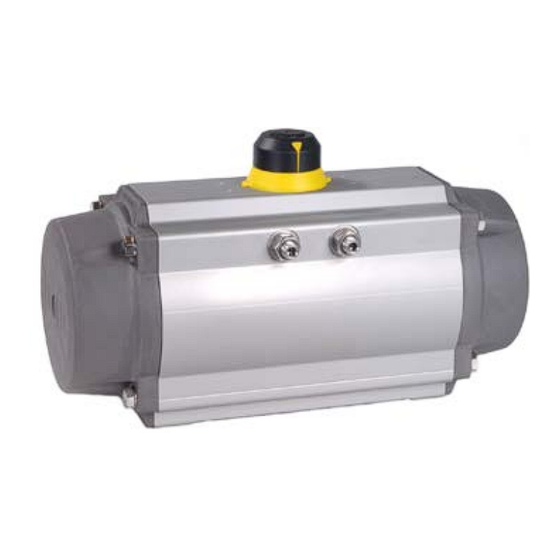
BR 31a Rack-and-pinion Actuator,
Fig. 1 - Rack-and-pinion actuator
0. Contents
1.
2.
3.
4.
4.1
4.2
4.3
4.4
4.5
4.6
4.7
4.8
4.9
5.
5.1
5.2
5.3
5.4
5.5
5.6
5.7
6.
6.1
(version manufactured from 2000)
6.2
7.
8.
1 of 18
Specifications subject to change without notice
Edition: August 2017
SRP and DAP
1. General
These instructions are intended to support the user in the
assembly, maintenance, and repair of BR 31a Rack-and-
pinion Actuators.
Before operating the unit, please read this manual thoroughly
and retain it for future reference.
Technical specifications, as a result of further development of
valves mentioned in these instructions are subject to
alteration without notice.
The text and illustrations do not necessarily display the scope
of supply or any ordering of spare parts.
Drawings and graphics are not to scale. Customer-specific
designs not in accordance with our standard product range
are not shown.
Parts subject to wear are not covered by the warranty.
1
1
1
2
2
2
3
In these maintenance and assembly instructions, the term
3
skilled staff refers to individuals who are able to judge the
3
responsibilities assigned to them as well as recognize
3
potential hazards due to their specialized training,
3
knowledge, and experience as well as their special
3
knowledge of the relevant standards.
3
These instructions apply to the actuator only. In addition,
4
refer to the instructions of the mounted valve.
4
4
4
5
2. Design, principle of operation, and
5
dimensions
5
6
Design, principle of operation, and dimensions including all
6
further details and technical data can be found in the Data
6
Sheet <TB 31a>.
7
3. Actuator designation and nameplate
13
The actuator type, size, operating pressure, output torque,
18
direction of rotation, fail-safe action, operating temperature,
18
and type of attachment are determined by the actuator
designation.
The device may only be mounted and started
up by skilled staff who are familiar with the
assembly, start-up, and operation of this
product.
Maintenance EB 31a-01_EN
Advertisement
Table of Contents

Related Manuals for Samson BR 31a Series


Summary of Contents for Samson BR 31a Series
-
Page 1: Table Of Contents
Operating, assembly and maintenance instructions BR 31a Rack-and-pinion Actuator, SRP and DAP 1. General These instructions are intended to support the user in the assembly, maintenance, and repair of BR 31a Rack-and- pinion Actuators. Before operating the unit, please read this manual thoroughly and retain it for future reference. -
Page 2: Operating Conditions
• Maximum permissible pressure (fixed) Always 10 bar for BR 31a • Principle of operation (variable) Actuator function: Single-acting/double-acting Direction of action: CW = Clockwise CCW = Counterclockwise Schematic diagram of the spring function with the air connection. Schematic diagram of NAMUR interface with identification for ports 2 and 4 •... -
Page 3: Operating Media
• Do not operate the actuator outside the temperature Note: For operation at low and high temperatures, limits: this could damage internal and external special lubricant is required. Please contact components (disassembly of single-acting actuators may Pfeiffer. A low or high temperature can slightly be dangerous). -
Page 4: Function And Direction Of Rotation
4.10 Function and direction of rotation: • Fail-open: counterclockwise (SRP only) The actuator is a pneumatic component for remote actuation of valves. For the actuation (90°, 120° or 180° rotation), there are different actuator versions: • Direct mounting of a solenoid valve (5/2 or 5/3-way for double acting, 3/2-way for single acting) for connecting to ports 2 and 4. -
Page 5: Important Safety Instructions
Air supplied to port 2 (Fig. 5) forces the pistons apart and Control and connections: towards the end positions. Air is vented at port 4. This is based on a clockwise direction of rotation. Air supplied to port 4 (Fig. 6) forces the pistons together. Air is vented at port 2. -
Page 6: Mounting The Actuator Onto Valves
Mounting the actuator onto valves: Changing the direction of action/fail-safe position Note: For the exact procedure for disassembly and assembly, refer to section 6 (maintenance and assembly instructions). • Move the actuator to the fail-safe position to release the spring compression. •... -
Page 7: Maintenance And Assembly Instructions
Fourth generation of rack-and-pinion actuators (version manufactured from 2000) 6.1.1 Screw sizes Actuator SW 1 SW 2 SW 3 SW 4 DAP/SRP in mm in mm in mm in mm in mm 1200 2000 3000 4000 Fig. 12 - Clockwise direction to close 5000 10000 Allen 14... - Page 8 Fig. 15 - Detailed drawing of Series 31a Actuator, version manufactured from 2010 Item Qty. Description Material Item Qty. Description Material Cam (end position adjustment) GS400-15 O-ring (piston) Adjusting screw A2-70 4 - 12 Spring cartridge SiCr spring steel Lock nut A2-70 Spring clip C 75...
- Page 9 ◦ 6.1.2 Disassembly of the actuator: For single-acting actuators, remove spring cartridge ( 17 ). When the actuator must be disassembled for maintenance ◦ Remove gasket ( 14 ) and renew it when replacing purposes, first remove the actuator from the valve. spare parts.
- Page 10 • Removing the pistons: (see Fig. 19) ◦ Clamp the housing ( 29 ) in a vise or similar device. Turn the shaft ( 30 ) until the pistons ( 25 ) are accessible. Note: Do not apply air pressure to remove the pistons from the housing (projectile impact).
- Page 11 Fig. 23 Fig. 22a Fig. 24 Fig. 22a Note: For actuators from 2006: The adjusting screws ( 2 ) of this actuator version are mounted from the inside, into the actuator housing. This step must carried out before the piston and end caps are mounted.
- Page 12 • Mounting the end caps (see Fig. 27, Fig. 28 and Fig. 29) For actuator sizes 900 to 3000, the end caps ( 22 and 23 ) and spring cartridges ( 17 ) are symmetric (Figs. 27, 28 and 29). ◦...
-
Page 13: Third Generation Rack-And-Pinion Actuators
• Mounting the position indicator (see Fig. 31) ◦ Place the position indicator ( 19 ) on the shaft, making sure that it is in the correct position. ◦ Tighten screw ( 24 ). Fig. 32 Fig. 31 The actuator assembly is now completed. Third generation rack-and-pinion actuators 6.2.1 Actuator disassembly... - Page 14 • O-ring replacement (with stop screw OPEN) • (see Fig. 35) ◦ Undo nut ( 12 ) using a socket wrench. ◦ Unthread the adjusting screw ( 10a ) and remove the washer ( 11a ) and O-ring ( 11 ). This must be done on both sides.
- Page 15 Fig. 39 - Detailed drawing of BR 31a Actuator, third generation Item Qty. Description Material Item Qty. Description Material Housing AlMgSi0,5 F25 Lock nut X5 CrNi 18 10 Piston GD-AlSi8 Cu3 Screw (end cap) X5 CrNi 18 10 End cap GD-AlSi8 Cu3 Washer X5 CrNi 18 10...
- Page 16 6.2.2 Actuator reassembly after replacement of parts • Mounting the actuator shaft and bearing bushings (see Fig. 40, Fig. 41, Fig. 42, and Fig. 43) ◦ Apply grease to the shaft as shown in Fig. 40. ◦ Push the top bearing bushing ( 6 ) onto the shaft ( 4 ). ◦...
- Page 17 ◦ Push and turn the housing onto the pistons clockwise until the end of travel is reached. Check that the internal angle adjusting screw does not reduce the travel. This is not necessary if it is to be 90° to 95°. ◦...
-
Page 18: Storage Instructions
7. Storage instructions Size: 15, 30, 60, 100, 150, 220, 300, 450, 600, 900, 1200, 2000, 3000, 4000, lf the actuators are not for immediate use, the following 5000 oder 10000 measures must be taken: Number of springs: only with single-acting Type SRP •...
Need help?
Do you have a question about the BR 31a Series and is the answer not in the manual?
Questions and answers