
Related Manuals for Samson ROTACTOR RP 3171


Summary of Contents for Samson ROTACTOR RP 3171
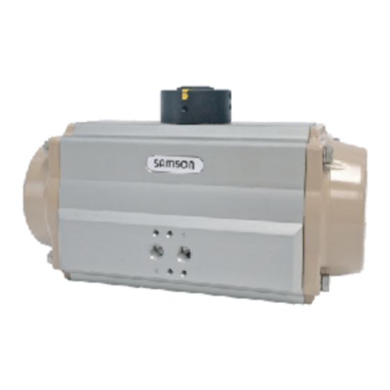
- Page 1 EB 8325 EN Original instructions SAMSON ROTACTOR RP 3171 ® Pneumatic rack and pinion actuators AT045U → AT801U models Edition May 2022...
- Page 2 Note on these mounting and operating instructions These mounting and operating instructions assist you in mounting and operating the device safely. The instructions are binding for handling SAMSON devices. The images shown in these instructions are for illustration purposes only. The actual product may vary.
-
Page 3: Table Of Contents
Contents Safety instructions and measures ......................... 1-1 Notes on possible severe personal injury ....................... 1-2 Notes on possible personal injury ......................... 1-2 Notes on possible property damage ......................1-2 Markings on the device ..........................2-1 Actuator nameplate sample .......................... 2-1 Design and principle of operation ........................ - Page 4 EB 8325 EN...
-
Page 5: Safety Instructions And Measures
Revisions and other modifications Revisions, conversions or other modifications of the product Intended use are not authorized by SAMSON. They are performed at the The SAMSON ROTACTOR RP 3171 actuators are designed user‘s own risk and may lead to safety hazards, for example. -
Page 6: Notes On Possible Severe Personal Injury
In case of pneumatic version the actuator is operated with air. SAMSON. As a result, air is exhausted during operation. − The SAMSON actuators are in compliance with the TR CU Î Install the air exhaust components in such a way that 10/2011 and TR CU 12/2011. - Page 7 Risk of actuator damage due to the use of unsuitable lubri- cants. The lubricants to be used depend on the actuator material and operating temperatures. Unsuitable lubricants may corrode and damage the components. Î Use only lubricants approved by SAMSON . Refer to sec- tion 15.3 ‘Lubricants‘. EB 8325 EN...
- Page 8 Safety instructions and measures EB 8325 EN...
-
Page 9: Markings On The Device
Markings on the device 2 Markings on the device 2.1 Actuator nameplate sample ATEX 2014/34/EU: n° INERIS-EQEN 034870/19 UKSI 2016:1107 : CML 21UKEXT1358 II 2 G Ex h IIC T6...T5 Gb X II 2 D Ex h IIIC T85°C...T95°C Db X Model / Type: SB AT304U S12 B EN ISO 5211:... - Page 10 Markings on the device Note Refer to the Catalogue T 8325 for actuators available options and ordering codes. EB 8325 EN...
-
Page 11: Design And Principle Of Operation
The actuators can be controlled by different options: − direct mounting of control devices (for example a solenoid The SAMSON ROTACTOR RP 3171 actuators are devices for valve or a manifold) with NAMUR interface, remote operation (on/off or modulating duties) of different in- −... -
Page 12: Complementary/Accessory Parts
NOTICE − In case of pressure medium different than Group 2 fluids Risk of actuator damage due to incorrect gearbox stroke according to the PED 2014/68/EU, contact SAMSON. adjustment. − Make sure that the actuator and the gearbox are correctly −... -
Page 13: Shipment And On-Site Tranport
The actuator can be transported using proper lifting equip- 2. Check the shipment for transportation damage. Report ment (e.g. crane or forklift). any damage to SAMSON and the forwarding agent (re- Î Leave the actuator in its transport container or on the pal- fer to delivery note). -
Page 14: Storing The Actuator
Î Observe the storage instructions. Î Observe the rubber components storage instructions (T 3.3.3.1 EN). Î Avoid long storage times. Contact SAMSON in case of different storage conditions or long storage periods. Note It is recommended to regularly check the actuator and the pre- vailing storage conditions during long storage times. -
Page 15: Mounting And Assembly
Î Do not impede the movement of the pinion and the pistons The SAMSON ROTACTOR RP 3171 actuators can be control- by inserting objects into the actuator. led by directly mounted devices or remote control systems. Th- erefore SAMSON actuators have direct mounting interfaces (Fig. - Page 16 Mounting and assembly Before mounting the actuator over the valve, make sure the − When fitting accessories over the actuators, assemble following conditions are met: them in such a way that the emergency controls are easily accessible for emergency manual operation. −...
- Page 17 Mounting and assembly 6. Place the bracket, if any, over the valve flange, tighten all bolts and nuts and apply the correct tightening torque. 7. Assemble the coupling at first into the valve stem before the assembly of the actuator. 8.
- Page 18 Mounting and assembly EB 8325 EN...
-
Page 19: Start-Up
Start-up 6 Start-up The work described in this section is only to be performed by fully trained and qualified personnel. WARNING Risk of personal injury during actuator air exhaust. In case of pneumatic version the actuator is operated with air. As a result, air is exhausted during operation. - Page 20 Start-up EB 8325 EN...
-
Page 21: Operation
Operation 7 Operation The actuator can be operated after connecting it to the supply line and adjusting the stroke. The work described in this section is only to be performed by Spring return actuators work on air stroke or spring stroke by fully trained and qualified personnel. - Page 22 Operation EB 8325 EN...
-
Page 23: Malfunctions
In case of actuator mounted over the valve, check the valve documentation Faulty valve and contact the manufacturer. Note Contact SAMSON after-sales service (samson@samsongroup.com) for malfunctions not listed in the table. 8.2 Emergency action The plant operator is responsible for emergency action to be taken in the plant. - Page 24 Malfunctions...
-
Page 25: Service
3. Remove the actuator from the valve referring to section 11 prior agreement by SAMSON‘s After-sales Service. ‘Removal‘. − Only use original spare parts by SAMSON, which comply with the original specifications. EB 8325 EN... -
Page 26: Part List
Service 9.2 Part list 41 08* 19.1 19.0 02 04 03 11* 08* 10 221G 17.3 222G 17.2 17.1 19.5 19.6 19.2 60.1 Fig. 9-1 Table 9-2 PART N° UNIT Q.TY NOTE DESCRIPTION N.A. for AT045U OCTI-CAM (Stop arrangement) N.A. for AT045U STOP CAP SCREW N.A. - Page 27 Service PART N° UNIT Q.TY NOTE DESCRIPTION ◊ BEARING (Pinion top) ◊ BEARING (Pinion bottom) ◊ 1 pcs for AT045U THRUST BEARING (Pinion) ◊ • N.A. for AT801U PLUG 09.1* ◊ • O-RING (For AT801U) THRUST WASHER (Pinion) ◊ • N.A.
-
Page 28: Disassembly
Service 9.3 Disassembly Refer to Fig. 9-1 and Fig 9-3. − Remove both stop cap screws (02) together with nuts (04) Î Refer to the Fig. 9-1 and Table 9-2 for parts list. and washers (03). − Remove the stop caps o-rings (11). 9.3.1 Position indicator and graduated In case of actuator with extra travel stop adjustment (Fig. - Page 29 (13) for the number of turns in- dicated in Table 9-3, the spring cartridge may have been Fig. 9-7 damaged or the pistons are not completely closed: stop the disassembly and contact SAMSON. EB 8325 EN...
-
Page 30: Service Operations
(08). operating temperatures. − Apply downward force to the top of the drive shaft Î Only use lubricants approved by SAMSON. Refer to secti- (60/60.1), until it is partially out of the bottom of the body on 15.3 ‘Lubricants‘. - Page 31 Pistons reassembly Refer to Fig. 9-1, Fig 9-12, Fig 9-13 and Fig 9-14. Proceed as follows to reassemble standard SAMSON ROTAC- TOR RP 3171 actuator pistons with a 90° angle of rotation and clockwise to close. Refer to the technical data sheet T 8325 in case of actuators with different function/rotation.
- Page 32 Service 40° - 45° 221G 222G Fig. 9-16 Fig. 9-14 − Place the end caps o-ring (14) into the groove as shown in − With pistons completely closed (0° position) as per Fig. Fig. 9-17 making sure that the o-ring is stable in its 9-15, referring to the axis of the body, the rotation ob- housing.
- Page 33 Service Î Assemble the end caps as shown in Fig. 9-20 keeping a 3 (red) 3 (red) constant distance (A = B) between the actuator body and 3 (red) 1 (green) 2 (black) the end cap interface. 1 (green) 2 (black) 1 (green) 2 (black) Î...
- Page 34 Service Close position − Fasten the indicator screw (39), if any. (Fig. 9-23) − With the actuator in close position (0° position) referring to Fig. 9-15 for pistons position, screw or unscrew the 19.1 right stop screw (02) 1 turn at a time until the desired stop position is achieved.
-
Page 35: Decommissioning
Decomissioning 10 Decomissioning To decommission the actuator for service work or before re- moving it from the valve, proceed as follows: The work described in this section is only to be performed by 1. Put the valve and its accessories out of operation in a safe fully trained and qualified personnel. - Page 36 Decomissioning 10-2 EB 8325 EN...
-
Page 37: Removal
Removal 11 Removal WARNING The work described in this section is only to be performed by Risk of personal injury due to preloaded and compressed fully trained and qualified personnel only. springs. End caps are under tension due to compressed springs. Before removing from the valve, make sure the actuator is put Furthermore incorrect spring cartidges disassembly could re- out of operation. - Page 38 Removal Proceed as follows to remove the actuator from the valve re- ferring to Fig. 11-1, making sure to not expose the plant to any risk: 1. Disconnect any electrical/pneumatic/hydraulic power supply from the actuators and make sure the actuator itself is depressurized.
-
Page 39: Repairs
NOTICE Risk of actuator damage due to incorrect repair work. Î Do not perform any repair work on your own. Î Contact SAMSON after-sales service (samson@samsongroup.com) for repair work. EB 8325 EN 12-1... - Page 40 Repairs 12-2 EB 8325 EN...
-
Page 41: Disposal
Disposal 13 Disposal At the end of their life cycle SAMSON actuators can be com- pletely disassembled and disposed sorting the components by the different materials. Î Observe local, national and international refuse regula- tions. All materials have been selected in order to ensure minimal... - Page 42 Disposal 13-2 EB 8325 EN...
-
Page 43: Certificates
Certificates 14 Certificates The following certificates and documents are available from SAMSON: − EU Declaration of Conformity (page 14-2), − ATEX Directive 2014/34/EU, − SIL Certification, − Machine Directive 2006/42/EC, − DNV Type Approval − IP67 and IP68 Degree of protection, −... - Page 44 AIR TORQUE S.p.A. Doc. n° ECDDUE via dei Livelli di Sopra, N° 8/11 24060 Costa di Mezzate (Bg) Italy Tel.: +39 035 682299 Fax: +39 035 687791 Issued: 01/2022 - Pag: 1/1 E-mail: info@airtorque.it EU / UK DECLARATION OF CONFORMITY In accordance with Machinery Directive 2006/42/EC and U.K.
-
Page 45: Annex
Annex 15 Annex 15.1 Tools 15.1.1 Tools list − WRENCH − CIRCLIP PLIER − TORQUE WRENCH − ALLEN KEY − SCREWDRIVER Fig. 15-1 15.1.2 Tools dimensions − Stop screws (02) and nuts (04); end cap screws (13). ACTUATOR MODEL Ch 1 (mm) Ch 2 (mm) AT045U AT051U... - Page 46 Annex − Extra travel stop adjustment screws tools (50% and 100% adjustment) Ch 4 ACTUATOR 221G/222G MODEL TYPE Ch 3 (mm) Ch 4 (mm) AT051U AT101U AT201U AT251U AT301U AT351U Ch 3 − Type A AT401U AT451U AT501U AT551U 221G 222G AT601U AT651U...
-
Page 47: Tightening Torque
Annex 15.2 Tightening torques − All the tightening torques are intended in Nm. − Tightening torque tolerance: ±10%. − The tightening torques are based on a friction coefficient of 0.12 with a lubricated fixing elements (bolts or nuts) threads. − After long operating times or use at temperatures above 80°C, the breakaway torque may be significantly higher. Table 15-1: End cap screws (13) Table 15-2: Extra travel stop adjustment nuts (04R) ACTUATOR MODEL... -
Page 48: Lubricants
NOTE: 1. Refer to section 2.1 ‘Actuator nameplate sample‘. 15.3 Lubricants The SAMSON ROTACTOR RP 3171 actuators are factory lubricated for the life of the actuator in normal working conditions. Î Refer to the data sheet [T 8325] for lubricant type in rela- tion to the different working temperature ranges. -
Page 49: Rubber Products Storage Instructions
(and any other kit with rubber products) properly stored maximum storage life by about 50% and storage at a 10°C into the original SAMSON packaging. In this case the rubber (18°F) lower temperature will increase the maximum storage products should be inspected and tested before the storage life by about 100%. - Page 50 Spare parts and kits with rubber components or testing and re-stored for a further storage period, they If not otherwise specified, the SAMSON spare parts and kits should be repackaged according to this document or with the with rubber components are packaged in polyethylene trans- same original packaging.
- Page 51 The SAMSON Rack and pinion and actuators are packaged in carton boxes and carton or wooded cases. Store all the SAMSON products according to the related IMAT maintenance instruction manuals in order to guarantee the correct product functions and performance.
- Page 52 16-4 EB 8325 EN...
- Page 53 EB 8325 EN 16-5...
- Page 54 EB 8325 EN SAMSON AKTIENGESELLSCHAFT Weismüllerstraße 3 · 60314 Frankfurt am Main, Germany Phone: +49 69 4009-0 · Fax: +49 69 4009-1507 samson@samsongroup.com · www.samsongroup.com...
Need help?
Do you have a question about the ROTACTOR RP 3171 and is the answer not in the manual?
Questions and answers