Samson 3271-5 Mounting And Operating Instructions
Pneumatic actuators
Hide thumbs
Also See for 3271-5:
- Mounting and operating instructions (66 pages) ,
- Mounting and operating instructions (70 pages) ,
- Mounting and operating instructions (48 pages)

Related Manuals for Samson 3271-5


Summary of Contents for Samson 3271-5
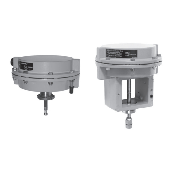
- Page 1 Pneumatic Actuators Type 3271‑5 (120 cm²) Type 3277‑5 (120 cm²) Type 3271 Pneumatic Actuator Type 3277 Pneumatic Actuator Mounting and Operating Instructions EB 8310-1 EN Edition April 2016...
- Page 2 Î For the safe and proper use of these instructions, read them carefully and keep them for later reference. Î If you have any questions about these instructions, contact SAMSON‘s After-sales Service Department (aftersalesservice@samson.de). The mounting and operating instructions for the devices are included in the scope of delivery.
-
Page 3: Table Of Contents
Mounting the actuator onto the valve .............24 5.1.1 Mounting onto Series 240 Valves ..............24 5.1.2 Mounting onto Type 3510 Micro-flow Valve ...........27 Connecting the signal pressure ..............28 5.2.1 Type 3271-5 ....................28 5.2.2 Type 3277-5 ....................29 Adapting the travel range ................29 Additional fittings ..................30 Operation ....................31 Throttling service ..................31 On/off service .....................31... - Page 4 Contents Reversal of the direction of action ..............32 6.3.1 Reversal of the direction of action from stem extends to stem retracts ....32 6.3.2 Reversal of the direction of action from stem retracts to stem extends ....34 Travel stop ....................36 6.4.1 Bottom travel stop (minimum travel) ...............36 6.4.2 Top travel stop (maximum travel) ..............36...
-
Page 5: Safety Instructions And Measures
SAMSON must be con- tacted. SAMSON does not assume any liability for damage resulting from the failure to use the de- vice for its intended purpose or for damage caused by external forces or any other external factors. - Page 6 Î Check with the plant operator for details on further protective equipment. Revisions and other modifications Revisions, conversions or other modifications to the product are not authorized by SAMSON. They are performed at the user's own risk and may lead to safety hazards, for example. Fur- thermore, the product may no longer meet the requirements for its intended use.
- Page 7 Safety instructions and measures Referenced standards and regulations According to the ignition risk assessment performed in accordance with EN 13463-1:2009, section 5.2, the non-electrical actuators do not have their own potential ignition source even in the rare incident of an operating fault. As a result, they do not fall within the scope of Di- rective 94/9/EC.
-
Page 8: Notes On Possible Severe Personal Injury
Safety instructions and measures 1.1 Notes on possible severe personal injury DANGER Risk of bursting in the actuator. Actuators are pressurized. Improper opening can lead to actuator components burst- ing. Î Before starting any work on the actuator, depressurize all plant sections concerned and the actuator. -
Page 9: Notes On Possible Property Damage
Risk of actuator damage due to the use of unsuitable tools. Certain tools are required to work on the actuator. Î Only use tools approved by SAMSON (u AB 0100). Risk of actuator damage due to the use of unsuitable lubricants. The lubricants to be used depend on the actuator material. Unsuitable lubricants may corrode and damage the valve surface. -
Page 10: Markings On The Device
12 Symbol indicating fail-safe action Actuator stem extends (FA) Actuator stem retracts (FE) 14 Connecting thread 15 Diaphragm material 16 Date of manufacture Made in Germany SAMSON 3271 Var-ID Serial no. Fig. 1: Nameplate of Type 3271 Actuator EB 8310-1 EN... - Page 11 Markings on the device EB 8310-1 EN...
-
Page 12: Design And Principle Of Operation
The stem connector clamps (A26/27) of The Type 3271-5 and Type 3277-5 Actua- Series 240 Valves connect the actuator stem tors have an actuator area of 120 cm². The (A7) with the plug stem of the valve. The... - Page 13 Design and principle of operation A20/21 A5.2 A5.1 A2.1 A2.1 A27.3 A27.1 A26/27 Version for micro-flow valve Legend for Fig. 2 and Fig. 3 Top diaphragm case A5.2 Diaphragm plate A27.1 Stem connector nut Bottom diaphragm case Actuator stem A27.3 Lock nut A2.1 Switchover/connecting Ring nut...
-
Page 14: Direction Of Action And Signal Pressure Routing
Design and principle of operation nection (A2.9) of the connecting plate to the 3.1 Direction of action and diaphragm chamber. signal pressure routing Note Actuators with device index .01 are The direction of action for both Type 3271 equipped with new connecting plates. Old and Type 3277 can be reversed (see sec- and new connecting plates are not inter- tion 6.3). -
Page 15: Versions
3.3 Versions ators can be fitted with an additional − Standard version handwheel. The handwheel is mounted The housings of Type 3271-5 and on the top diaphragm case and is used Type 3277-5 Pneumatic Actuators have to adjust the travel manually. -
Page 16: Technical Data
6 bar in throttling service. See section 6.2 Actuators bear the EAC mark of conformity. for restrictions in on/off service. Dimensions and weights See Table 1 and dimensional drawings on page 16 and 18. Dimensional drawings ØD ØD ØD2 Ød ØD2 Ød Type 3271-5 Type 3277-5 EB 8310-1 EN... - Page 17 Design and principle of operation Table 1: Dimensions in mm and weights in kg Actuator Type 3271-5 3277-5 Actuator area cm² rated Height – ØD Diameter ØD2 M30 x 1.5 M30 x 1.5 1) 1) Thread Ød G NPT) Air connection – Weight Without handwheel With handwheel In version for micro-flow valve: M20 x 1.5 thread...
- Page 18 Design and principle of operation Dimensional drawings ØD ØD ØD2 ØD2 Ød Ød Type 3271-5 with handwheel Type 3277-5 with travel stop ØD2 ØD2 M14 x 1 M14 x 1 Ød Ød Versions with 7.5 mm travel for Type 3510 Micro-flow Valve EB 8310-1 EN...
- Page 19 Design and principle of operation EB 8310-1 EN...
-
Page 20: Preparation
2. Check the shipment for transportation Transport instructions damage. Report any damage to − Protect the actuator against external in- SAMSON and the forwarding agent (re- fluences (e.g. impact). fer to delivery note). − Do not damage the corrosion protection (paint, surface coatings). -
Page 21: Storage
− Observe storage instructions. them up. − Avoid long storage times. − We recommend a storage temperature of − Contact SAMSON in case of different stor- 15 °C for elastomers. age conditions or longer storage times. − Store elastomers away from lubricants, chemicals, solutions, and fuels. -
Page 22: Preparation For Installation
Preparation 4.4 Preparation for installation Proceed as follows: Î Check the actuator for damage. Î Check to make sure that the type desig- nation, material, and temperature range of the actuator match the plant condi- tions. Î Check the pressure gauge installed on valve accessories to make sure it func- tions. - Page 23 Preparation EB 8310-1 EN...
-
Page 24: Mounting And Start-Up
5 Mounting and start-up 5.1 Mounting the actuator onto the valve SAMSON control valves are delivered ready for use. In special cases, the valve and actu- Proceed as follows if the valve and actuator ator are delivered separately and must be have not been assembled by SAMSON: assembled on site. - Page 25 Mounting and start-up Bonnet/flange Threaded bushing Stem connector nut Lock nut Travel indicator scale Actuator stem Ring nut A26/27 Stem connector A26/27 clamps Signal pressure connection Fig. 5: Type 3271 Pneumatic Actuator on a Series 240 Valve 6. Place the actuator onto the valve bonnet 9.
- Page 26 Mounting and start-up Yoke Plug stem with plug Travel indicator scale Bottom diaphragm case Actuator stem Ring nut A27.1 Stem connector nut A27.2 Bearing sleeve (bottom part of the stem connector) A27.3 Lock nut Fig. 6: Type 3277 Pneumatic A27.3 Actuator on a Type 3510 A27.1 Micro-flow Valve A27.2...
-
Page 27: Mounting Onto Type 3510 Micro-Flow Valve
Mounting and start-up In the "actuator stem retracts" version: 5.1.2 Mounting onto Type 3510 Micro‑flow fasten tight the stem connector nut (A27.1) at the bottom end of the actua- Valve tor stem (A7) to the bearing sleeve (A27.2) on the plug stem (5). 1. -
Page 28: Connecting The Signal Pressure
Mounting and start-up 5.2 Connecting the signal pressure Type 3271‑5 5.2.1 Version with fail-safe action "actuator stem Version with fail-safe action "actuator stem extends" (FA) retracts" (FE) Î Connect the signal pressure to the bottom Î Connect the signal pressure to the top signal pressure connection (S). -
Page 29: Type 3277-5
(A2.5). See Fig. 8. retracts" (FE) Î Make sure that the gasket for the con- When a SAMSON valve is combined with necting plate is correctly inserted. an oversized actuator (e.g. the rated travel Î The connecting plate has threaded holes of the actuator is larger than the rated travel with NPT and G threads. -
Page 30: Additional Fittings
Mounting and start-up 5.4 Additional fittings Vent plug Vent plugs are screwed into the exhaust air ports of pneumatic, electropneumatic, and electric devices. They ensure that any ex- haust air that forms can be vented to the at- mosphere (to avoid excess pressure in the device). -
Page 31: Operation
Operation 6 Operation 6.1 Throttling service The Type 3271-5 and Type 3277-5 Pneu- WARNING matic Actuators are designed for a maxi- Crush hazard arising from moving parts (ac- mum supply pressure of 6 bar when used for tuator stem). throttling service. Do not insert hands or finger into the yoke while the valve is in operation. -
Page 32: Reversal Of The Direction Of Action
After reversal, the symbol and configuration ID on the nameplate are no longer valid. 6. Remove the diaphragm plate (A51), dia- Contact SAMSON to request a new name- phragm (A4), and diaphragm plate plate. (A5.2) from the actuator stem (A7) and... - Page 33 Operation A15 A9 Fig. 9: Type 3271-5 and Type 3277-5 Pneumatic Actuators A5.1 A5.2 Type 3271-5 A20/21 A2.1 Type 3277-5 Top diaphragm case Actuator stem Hexagon nut Bottom diaphragm case Ring nut Radial shaft seal A2.1 Switchover/connecting Hexagon nut Wiper ring plate for signal pressure...
-
Page 34: Reversal Of The Direction Of Action From Stem Retracts To Stem Extends
Operation 8. Apply a suitable lubricant to the actuator 6.3.2 Reversal of the direction stem (A7). of action from stem re- 9. Place the springs (A10) in the bottom di- tracts to stem extends aphragm case (A2), centering them in the intended recesses. - Page 35 Operation (A5.2) in the bottom diaphragm case The actuator springs, which now push against the diaphragm plate from above, (A2). cause the actuator stem to extend. The 11. Place the springs (A10) in the bottom di- signal pressure is connected to the bot- aphragm case (A2), centering them in tom connection (S) on the bottom dia- the intended recesses.
-
Page 36: Travel Stop
A stem connector (A51) links the handwheel and actuator stem. The actuator stem posi- tion can be adjusted using the handwheel (A60). See Fig. 11. Note If you want to fit a handwheel to an actuator, contact SAMSON's After-sales Service de- partment. EB 8310-1 EN... - Page 37 Operation Stem connector Handwheel Fig. 11: Type 3271-5 Actuator with handwheel EB 8310-1 EN...
-
Page 38: Maintenance
Risk of actuator damage due to the use of unsuitable tools. DANGER Risk of bursting in the actuator. Only use tools approved by SAMSON Actuators are pressurized. Improper opening (u AB 0100). can lead to actuator components bursting. Before starting any work on the actuator, de-... - Page 39 Maintenance A15 A9 Fig. 12: Type 3271-5 and Type 3277-5 Pneumatic Actuators A5.1 A5.2 Type 3271-5 A20/21 A2.1 Type 3277-5 Top diaphragm case Actuator stem Radial shaft seal Bottom diaphragm case Ring nut Wiper ring A2.1 Switchover/connecting Hexagon nut Dry bearing plate for signal pressure...
-
Page 40: Replacing The Diaphragm
Maintenance 8. Check the sealing element of the collar 7.1 Replacing the diaphragm nut (A15). If necessary, renew it (order no. 8353-0533). 9. Apply a suitable lubricant to the actuator We recommend to also replace the actuator stem (A7). stem seal on replacing the diaphragm. See 10. -
Page 41: Replacing The Actuator Stem Seals
Maintenance 7.2 Replacing the actuator NOTICE stem seals Malfunction due to loosened nut. The nut (A9) on the actuator stem serves to adjust the dimension a. Do not undo the nut (A9). If the nut has come undone, readjust We recommend to also replace the dia- the dimension a according to Table 2 on phragm on replacing the actuator stem seal. -
Page 42: Determining Dimension A
Dimension a Type/version Travel [mm] on the diaphragm case. [mm] 3. Lift off the top diaphragm case (A1). 3271-5 100.75 4. Pull the actuator stem (A7) together with Type 3271-5 the diaphragm plate (A5.1), diaphragm for micro-flow (A4), and diaphragm plate (A5.2) out of valve the bottom diaphragm case (A2). -
Page 43: Preparation For Return Shipment
> Contact. 7.5 Ordering spare parts and operating supplies Contact your nearest SAMSON subsidiary or the SAMSON After-sales Service depart- ment for information on spare parts, lubri- cants, and tools. Spare parts See section 10.2 for details on spare parts. -
Page 44: Malfunctions
Depending on the operating conditions, check the actuator at certain intervals to prevent possible failure before it can occur. Operators are responsible for drawing up a test plan. SAMSON's After-sales Service department can support you to draw up a maintenance plan for your plant. - Page 45 Malfunctions EB 8310-1 EN...
-
Page 46: Decommissioning And Disassembly
Decommissioning and disassembly 50 % of the bench range to the actuator. 9 Decommissioning and disas- Undo the ring nut (A8). Disconnect the sembly signal pressure. In the "actuator stem retracts" version: DANGER undo ring nut (A8). Risk of bursting in the actuator. 5. -
Page 47: Disposal
Decommissioning and disassembly Note The bearing sleeve (A27.3) remains on the valve. 7. Fasten ring nut (A8) on the actuator. 9.3 Disposal Î Observe local, national, and internation- al refuse regulations. Î Do not dispose of components, lubri- cants, and hazardous substances togeth- er with your other household waste. -
Page 48: Appendix
Collar nut partment at aftersalesservice@samson.de. Hexagon bolt Addresses of SAMSON AG and its subsid- Hexagon nut iaries Washer The addresses of SAMSON AG, its subsid- 26/27 Stem connector clamps iaries, representatives, and service facilities 2) 27.1 Stem connector nut worldwide can be found on the SAMSON 2) - Page 49 26/27 Stem extends (FA) Stem retracts (FE) Stem extends (FA) Stem retracts (FE) 26/27 Type 3271-5 and Type 3277-5 Actuators, 120 cm² EB 8310-1 EN...
- Page 50 27.3 27.1 Stem extends (FA) Stem retracts (FE) Stem extends (FA) Stem retracts (FE) 27.3 27.1 Type 3271-5 and Type 3277-5 Actuator, 120 cm², as version for micro-flow valve EB 8310-1 EN...
- Page 51 EB 8310-1 EN...
- Page 52 SAMSON AG · MESS- UND REGELTECHNIK Weismüllerstraße 3 · 60314 Frankfurt am Main, Germany Phone: +49 69 4009-0 · Fax: +49 69 4009-1507 EB 8310-1 EN samson@samson.de · www.samson.de...
Need help?
Do you have a question about the 3271-5 and is the answer not in the manual?
Questions and answers