
Subscribe to Our Youtube Channel
Related Manuals for Stahl ethernet-apl 9740 Series


Summary of Contents for Stahl ethernet-apl 9740 Series
- Page 1 Operating instructions Additional languages r-stahl.com Ethernet-APL Field Switch for Zone 1 and Zone 2 Series 9740...
-
Page 2: Table Of Contents
Contents General Information ....................3 Manufacturer ......................3 About these Operating Instructions ................ 3 Further Documents....................3 Conformity with Standards and Regulations ............3 Explanation of Symbols ..................4 Symbols used in these Operating Instructions ............4 Symbols on the device ................... 4 Identification of the device .................. -
Page 3: General Information
• Make the operating instructions accessible to operating and maintenance staff at all times. • Pass the operating instructions on to each subsequent owner or user of the device. • Update the operating instructions every time R. STAHL issues an amendment. ID no.: 330362 / 974060310010 Publication code: 2024-11-12·BA00·III·en·00... -
Page 4: Explanation Of Symbols
Marking according to WEEE Directive 2012/19/EU Component prone to electrostatic charges! Observe the safety notes and handling instructions in these operating instructions. 2.3 Identification of the device Manufacturer address: R. STAHL, 74638 Waldenburg, r-stahl.com Place of production: Made in Germany Barcode: internal use Serial number:... -
Page 5: Typographic Conventions
2.4 Typographic conventions The following conventions are used throughout this documentation: Open Start → Control Panel → Keys, buttons, menu items, commands and other elements involving user Programs interaction are set in bold font and menu sequences are separated by an arrow. Buttons from the user interface are Press [Start] to start the application enclosed in brackets and set to bold... -
Page 6: Residual Risks
(see the "Technical data" chapter). ► Do not place any loads on the device. ► Check the packaging and the device for damage. Report any damage to R. STAHL immediately. Do not commission a damaged device. Ethernet-APL Field Switch... - Page 7 ► Store the device in its original packaging in a dry place (with no condensation), and make sure that it is stable and protected against the effects of vibrations and knocks. ► Observe the ambient temperature when storing the device (see the "Technical data"...
-
Page 8: Transport And Storage
Opening the device will void the warranty and the explosion protection! ► Repair work on the device must be performed only by R. STAHL Transport and storage ► Transport and store the device carefully and only in accordance with the safety information (see "Safety"... -
Page 9: Supported Features
Product Selection There are four version of the Ethernet-APL Field Switches available: Type Instal- Ethernet- Ethernet-connections Integrated lation APL spurs PA-Proxy 9740/13-16-01 Zone 2 12A+4AB 2 x TX (Ex ec) + 2 x FX (SFP ) No 9740/13-16-41 Zone 2 16A 2 x TX (Ex ec) + 2 x FX (SFP ) Yes 9740/12-16-00... -
Page 10: System Requirements
• Support of Ethernet-APL ports according Power Class A and B (see “product selection”). • PA Proxy function for mixed use of Ethernet-APL and PROFIBUS PA devices per spur (see “product selection”). • PROFINET Conformance Class B support incl. S2 redundancy and MRP. •... -
Page 11: Mounting And Installation
Mounting and installation NOTICE Make sure the Ethernet-APL Field Switch is mounted in such a way that the power supply can be easily disconnected. CAUTION Installation and inspection must be carried out by qualified personnel only (personnel qualified according to the IEC 60079-14 and IEC 60079-17 or equivalent local standards). -
Page 12: Installation
Use the top left screw to connect the field switch to your safety grounding/potential equalization network: Dismounting DANGER! Explosion hazard due to plugging or unplugging cables in an explosive atmosphere! Non-compliance may result in serious or fatal injuries. ► Do not connect or disconnect non-intrinsically safe connectors during operation in potentially explosive atmospheres! Disconnect all connections including the grounding cable . - Page 13 6.2.1 Connection of power supply Two connections “PWR1” and “PWR2” are available for a primary and optionally a redundant power supply. The connectors shall not be plugged or unplugged during the device is in operation in a potentially explosive atmosphere. Supply Connection Rated Voltage PWR1...
- Page 14 The SFP modules shall not be plugged or unplugged during the device is in operation in a potentially explosive atmosphere. Only use SFP modules that have been approved by R. STAHL (see accessories). ► The SFP modules are sensitive to electrostatic discharges. Damages due to electrostatic discharge can lead to premature failure of components or intermittent faults at a later stage.
- Page 15 The Zone 1 Field Switches use terminal connectors with 5 pins. These connectors are compliant to IEC 60079-7 (Increased safety “eb”) for Zone 1 installations. The pin assignment for an Ethernet cable is depicted below. XT1-3 RJ45 Signal PROFINET EIA/TIA T568A EIA/TIA T568B n.a.
-
Page 16: Commissioning And Configuration
NOTICE Ethernet-APL is not polarity sensitive, + and – can be swapped in general. However, watch the instruction manual of the Ethernet-APL field devices that should be connected to the field switch. Connecting the spur cable shield The Ethernet-APL Field Switch provides an integrated capacitive shielding connection at the spur terminals “S”. -
Page 17: Powering Up The Device
7.1 Powering up the device Turn on the power supply. The boot process takes approx. 20 seconds, please wait while the green “BOOT” Status-LED is ON. Do not remove power during boot process. The device is ready when the “BOOT” Status-LED is off and at least one green PWR LED is on. -
Page 18: Display
7.3 Display The Ethernet-APL Field Switch has a display (OLED) with touch buttons on the top right side for a detailed overview of status information and diagnostics data. A detailed description of the display and its content can be found in the Software Manual. Following an overview. -
Page 19: Ip Address Identification
7.5 Changing the IP address using the APL Detect Tool The APL Detect Tool can scan the Ethernet Network for connected Ethernet-APL Field Switches and displays the IP addresses of the found R. STAHL field switches. This applies also to field switches which are outside of the IP-addressable address range of the network. -
Page 20: Changing The Ip Address Using A Pc
7.6 Changing the IP address using a PC To access the Ethernet-APL Field Switch from a PC, you may have to change the default IP address via the integrated web server to an address on your network or change the DHCP address on the PC to a static IP address that matches the network address of the gateway (e.g. -
Page 21: Ip Address Settings Via Profinet
For further details refer to the Software Manual. 7.7 IP address settings via PROFINET The field switch starts up with the preconfigured IP address 192.168.0.10, a name based on its MAC address (e.g. “node-00-06-71-xx-yy-zz.local”) and enabled PROFINET communication capabilities. It can be accessed by any PROFINET engineering tool which supports PROFINET discovery and configuration protocol (PN- DCP). - Page 22 4. Release the reset button and wait approx. 10 seconds (BOOT LED is ON). 5. Press the reset button again and hold for approx. 20 seconds (BOOT LED is 6. Release the reset button. When the BOOT LEDs turn off after about a minute, the field switch is reset and reboots with the factory settings and factory IP address.
-
Page 23: Operation
Operation This chapter describes the basic activities in the webserver of the Ethernet-APL Field Switch. A detailed description of all available menus and functions can be found in the Software Manual. 8.1 Login The user interface of the Ethernet-APL Field Switch can be accessed via a web browser. - Page 24 You need to be logged in as administrator to initiate a firmware upgrade. Make sure you that have the new firmware file on your PC or download the latest version from the R. STAHL website. Log on to the web server of the field switch as described above.
- Page 25 Select Settings → Firmware Click [Choose Firmware File…] and select the firmware file with suffix .IMG (signed file) or .BIN (signed & encoded file). Click [Check] to verify the firmware: Click [Update] to install the firmware on the Ethernet-APL Field Switch. Press [OK] in the message pop-up window.
-
Page 26: Integration Into Profinet
2. Select [Erase Configuration] to reset your device to default settings. 3. Click [OK] to confirm your selection. Your Field Switch will be restarted with the default settings. NOTICE IP settings will not be deleted. The password is reset to the default password. 8.3 Integration into PROFINET The Ethernet-APL Field Switch is compliant with PROFINET Conformance Class B(PA) incl. - Page 27 NOTICE Various engineering systems only support a specific GSDML format. If your system is listed here, you should select it. Otherwise you can proceed with “generic”. 3. Enter a Plant name to the GSDML file. NOTICE In TIA Portal the plant name appears as a folder in the Device Catalogue after importing the GSDML file.
-
Page 28: Profibus Pa Devices
8.4 PROFIBUS PA devices Only supported by 9740/1*-16-4* The internal PROFIBUS PA Proxy allows the operation of PROFIBUS PA devices at the Ethernet-APL Field Switch. Each spur ports needs to be configured to Ethernet- APL or PROFIBUS PA via GSDML. On default, the spur ports are set to Ethernet-APL. To use PROFIBUS PA devices, configure the PROFIBUS PA segment on the Webserver and download the GSDML file. -
Page 29: Switch
8.5 Switch 8.5.1 Health Select Switch → Views → Health to monitor the port status of the 100 Mbit/s Ethernet trunks and the Ethernet-APL spurs. Each trunk and spur port are shown with the following information: general description of the port status: “connected”, “disabled” or “no device” State: link status information: “down”... -
Page 30: Maintenance, Overhaul, Repair
► Perform overhaul of the device according to the applicable national regulations and the safety notes in these operating instructions ("Safety" chapter). 9.3 Repair ► Repair work on the device must be performed only by R. STAHL. 10 Returning the Device ► Only return or package the devices after consulting R. STAHL! Contact the responsible representative from R. -
Page 31: Cleaning
► Fill out the form and send it. You will automatically receive an RMA form via email. Please print this file off. ► Send the device along with the RMA form in the packaging to R. STAHL Schaltgeräte GmbH (refer to chapter 1.1 for the address). -
Page 32: Technical Data
14 Appendix A 14.1 Technical Data 9740/13-16-01 9740/13-16-41 9740/12-16-00 9740/12-16-40 Explosion Protection Installation (Zones) 2, safe area 1, 2, safe area Ex interface Zone 0, 1, 2, 20, 21, 22 0, 1, 2, 20, 21, 22 IECEx certificate in preparation in preparation IECEx gas explosion protection Ex ec ia [ia Ga] IIC T4 Gc... - Page 33 9740/13-16-01 9740/13-16-41 9740/12-16-00 9740/12-16-40 Transfer rate spurs 10 MBit/s full duplex 10 MBit/s full duplex 10 MBit/s full duplex 10 MBit/s full duplex 31.25 kBit/s 31.25 kBit/s Power Class A, B A, B Max. number of spurs power class Max. number of spurs power class Max.
-
Page 34: Dimensions
14.2 Dimensions Dimension drawing (all dimension in mm [inch]) – subject to changes 14.3 Accessories Description Art.-No. Terminal set for 9740/13 305676 Version: Screw terminals Contents: 16 x 3- pole, blue; 2 x 4- pole, black Terminal set for 9740/13 305677 Version: Spring clamp terminals Contents: 16 x 3- pole, blue;... -
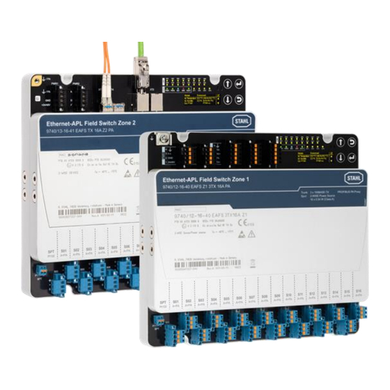
Page 35: Device Design Ethernet-Apl Field Switch
15 Appendix B 15.1 Device design Ethernet-APL Field Switch 9740/13 for Zone 2 installation 9740/12 for Zone 1 installation Device elements Description Connection for PA Phillips screw for connecting the field switch to the safety potential equalisation (PA) Connectors for power supply, Plug-in terminals PWR1, PWR2 with two locking screws primary and redundant Slots for SFP-modules... - Page 36 Ethernet-APL Field Switch for Zone 1 and 2 330362 / 974060310010 Series 9740 2024-11-12·BA00·III·en·00...
Need help?
Do you have a question about the ethernet-apl 9740 Series and is the answer not in the manual?
Questions and answers