Table of Contents
Advertisement
Available languages
Available languages
Quick Links
Advertisement
Chapters
Table of Contents

Subscribe to Our Youtube Channel
Related Manuals for Stahl 9721/13-42 Series


Summary of Contents for Stahl 9721/13-42 Series
- Page 1 Betriebsanleitung Operating instructions Additional languages www.stahl-ex.com DE EN Switch unmanaged FX op is SC / TX RJ45 für Zone 2 Unmanaged Switch FX op is SC / TX RJ45 for Zone 2 Reihe 9721/13-42-.. Series 9721/13-42-..
- Page 3 Betriebsanleitung Additional languages www.r-stahl.com Switch Unmanaged FX op is SC / TX RJ45 für Zone 2 Reihe 9721/13-42-..
-
Page 4: Table Of Contents
Inhaltsverzeichnis Allgemeine Angaben ...................3 Hersteller ......................3 Angaben zur Betriebsanleitung ................3 Weitere Dokumente ....................3 Konformität zu Normen und Bestimmungen ............3 Erläuterung der Symbole ..................4 Symbole in der Betriebsanleitung ...............4 Warnhinweise .....................4 Symbole am Gerät ....................5 Sicherheitshinweise ....................5 Qualifikation des Personals ................5 Sichere Verwendung ...................6 Umbauten und Änderungen ................7 Funktion und Geräteaufbau ................7... -
Page 5: Allgemeine Angaben
Betriebsanleitung während der Lebensdauer des Geräts aufbewahren. Betriebsanleitung dem Bedien- und Wartungspersonal jederzeit zugänglich machen. Betriebsanleitung an jeden folgenden Besitzer oder Benutzer des Geräts weitergeben. Betriebsanleitung bei jeder von R. STAHL erhaltenen Ergänzung aktualisieren. ID-Nr.: 251379 / 972160310080 Publikationsnummer: 2018-03-02·BA00·III·de·03 Die Originalbetriebsanleitung ist die englische Ausgabe. -
Page 6: Erläuterung Der Symbole
Erläuterung der Symbole Erläuterung der Symbole Symbole in der Betriebsanleitung Symbol Bedeutung Tipps und Empfehlungen zum Gebrauch des Geräts Gefahr durch explosionsfähige Atmosphäre Warnhinweise Warnhinweise unbedingt befolgen, um das konstruktive und durch den Betrieb bedingte Risiko zu minimieren. Die Warnhinweise sind wie folgt aufgebaut: •... -
Page 7: Symbole Am Gerät
Fachkräfte, die diese Tätigkeiten ausführen, müssen einen Kenntnisstand haben, der relevante nationale Normen und Bestimmungen umfasst. Für Tätigkeiten in explosionsgefährdeten Bereichen sind weitere Kenntnisse erforderlich! R. STAHL empfiehlt einen Kenntnisstand, der in folgenden Normen be- schrieben wird: • IEC/EN 60079-14 (Projektierung, Auswahl und Errichtung elektrischer Anlagen) •... -
Page 8: 3.2 Sichere Verwendung
• Bei Betriebsbedingungen, die durch die technischen Daten des Geräts nicht abgedeckt werden, unbedingt bei der R. STAHL Schaltgeräte GmbH rückfragen. • Vor Installation sicherstellen, dass das Gerät unbeschädigt ist. • Für Schäden, die durch fehlerhaften oder unzulässigen Einsatz des Geräts sowie durch Nichtbeachtung dieser Betriebsanleitung entstehen, besteht keine Haftung. -
Page 9: Umbauten Und Änderungen
Funktion und Geräteaufbau Umbauten und Änderungen GEFAHR Explosionsgefahr durch Umbauten und Änderungen am Gerät! Nichtbeachten führt zu schweren oder tödlichen Verletzungen. • Gerät nicht umbauen oder verändern. Für Schäden, die durch Umbauten und Änderungen entstehen, besteht keine Haftung und keine Gewährleistung. Funktion und Geräteaufbau GEFAHR Explosionsgefahr durch zweckentfremdete Verwendung! -
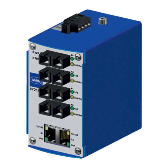
Page 10: 4.2 Geräteaufbau
Funktion und Geräteaufbau Geräteaufbau 17972E00 Gerätelement Beschreibung LED grün Statusanzeige Betriebszustand LED rot Statusanzeige Gerätefehler 2 x RJ45-Buchse für Kupfer-Ethernet LED grün Statusanzeigen RJ45 / LWL Port LED gelb Statusanzeigen RJ45 / LWL Port 4 x SC-Buchse für LWL-Ethernet Netzanschluss für Hilfsenergie Schraube für Erdung... - Page 11 Technische Daten Technische Daten Kennzeichnung Typbezeichnung 9721/13-42-e4 (e=1,5,7) CE-Kennzeichnung C 0158 Explosionsschutz Global (IECEx) Gas und Staub IECEx TUR 16.0002X Ex ec [op is T6 Ga] IIC T4 Gc [Ex op is Da] IIIC Europa (ATEX) Gas und Staub TÜV 16 ATEX 7742 X E II 3 (1) G Ex ec [op is T6 Ga] IIC T4 Gc E II (1) D [Ex op is Da] IIIC Bescheinigungen und Zertifikate...
-
Page 12: Technische Daten
Technische Daten Technische Daten Anzugs- 0,5 Nm drehmoment Schnittstelle TX Ethernet Ports 2 Ports 100BASE TX (Kupferleitung) Anschlussart RJ45-Steckverbinder Übertragungsrate 10/100 Mbit/s, Auto-Negotiation Betriebsart Halb; Voll Duplex Auto MDI/MDIX Übertragungs- bis 100 m (Cat5e oder besser) länge Anschluss FX LWL-Ethernet Ausführung 9721/13-42-14 9721/13-42-54... -
Page 13: Projektierung
Schutzart IP20 (IEC 60529) Schadstoffklasse entspricht G3 Weitere technische Daten, siehe www.r-stahl.com. Projektierung HINWEIS Ausfall der installierten Geräte im Schaltschrank durch zu hohe Umgebungstemperatur! Nichtbeachten kann zu Sachschäden führen. • Schaltschrank so aufbauen und einrichten, dass er immer innerhalb des zulässigen Temperaturbereichs betrieben wird. -
Page 14: Montage Und Installation
Montage und Installation • Gerät trocken (keine Betauung) und erschütterungsfrei lagern. • Gerät nicht stürzen. Montage und Installation Das Gerät ist für den Einsatz in gasexplosionsgefährdeten Bereichen der Zone 2, in staubexplosionsgefährdeten Bereichen der Zone 22 sowie auch im sicheren Bereich zugelassen. -
Page 15: Maßangaben / Befestigungsmaße
Montage und Installation Maßangaben / Befestigungsmaße Maßzeichnungen (alle Maße in mm [Zoll]) – Änderungen vorbehalten 17971E00 17971E00 Montage / Demontage, Gebrauchslage 8.2.1 Gebrauchslage Die Gebrauchslage ist beliebig. 251379 / 972160310080 Switch Unmanaged FX op is SC / TX RJ45 für 2018-03-02·BA00·III·de·03 Zone 2 Reihe 9721/13-42-.. - Page 16 Montage und Installation 8.2.2 Montage Montage auf Hutschiene • Mit dem vormontierten Montage-Clip (10) von unten an Hutschiene (11) ansetzen. Die Feder (9) muss hinter der Hutschiene liegen. • Gerät kräftig nach oben drücken und auf die Hutschiene einrasten. • Vergewissern, dass das Gerät sicher montiert ist.
-
Page 17: Installation
Montage und Installation Option 1: Frontale Entnahme • Switch kräftig nach oben drücken, bis sich der Montage-Clip (10) von der Hutschiene (11) löst. • Die Oberkante des Geräts nach vorne schwenken und das Gerät nach unten entnehmen. 17973E00 17974E00 Option 2: Seitliche Entnahme •... - Page 18 Montage und Installation 8.3.1 Hilfsenergie anschließen • Die Hilfsenenergie (Nennspannung = 24 V DC, VDC1 VDC2 siehe Datenblatt) an Klemmen VDC1 Earth (oder redundant VDC2) und GND anschließen. Dazu technische Daten und Anschlussquerschnitt der Leitungen beachten. 17479E00 • Steckbare Klemmen am Gerät mit Schrauben gegen Lockern sichern (Anzugsdrehmoment 0,5 ...
-
Page 19: Inbetriebnahme
Inbetriebnahme Inbetriebnahme GEFAHR Explosionsgefahr durch fehlerhafte Installation! Nichtbeachten führt zu schweren oder tödlichen Verletzungen. • Gerät vor der Inbetriebnahme auf korrekte Installation prüfen. • Nationale Bestimmungen einhalten. Vor Inbetriebnahme Folgendes sicherstellen: • Vorschriftsmäßige Installation des Gerätes. • Richtiger Anschluss der Kabel. •... -
Page 20: Betrieb
Betrieb 10.2 Anzeige Entsprechende LEDs am Gerät zeigen den Betriebszustand des Geräts an (siehe auch Kapitel "Funktion und Geräteaufbau"). Link/Act Link/Act 9721/13 Link/Act Link/Act 10/100 10/100 Link Link 17430E00 Farbe Bedeutung LED "PWR" grün Versorgungsspannung +24 VDC liegt an VDC1 oder VDC2 an LED "ERR"... -
Page 21: 10.3 Fehlerbeseitigung
Verbundenes Gerät prüfen einsatzbereit Switch defekt Switch ersetzen Wenn sich der Fehler mit den genannten Vorgehensweisen nicht beheben lässt: • An R. STAHL Schaltgeräte GmbH wenden. Zur schnellen Bearbeitung folgende Angaben bereithalten: • Typ und Seriennummer des Geräts • Kaufdaten • Fehlerbeschreibung •... -
Page 22: Instandhaltung, Wartung, Reparatur
• Reparaturen an den Geräten ausschließlich durch R. STAHL Schaltgeräte GmbH ausführen lassen. 11.4 Rücksendung Rücksendung bzw. Verpackung der Geräte nur in Absprache mit R. STAHL durchführen! Dazu mit der zuständigen Vertretung von R. STAHL Kontakt aufnehmen. Für die Rücksendung im Reparatur- bzw. Servicefall steht der Kundenservice von R. -
Page 23: Reinigung
Zubehör und Ersatzteile HINWEIS Fehlfunktion oder Geräteschaden durch den Einsatz nicht originaler Bauteile. Nichtbeachten kann Sachschaden verursachen! • Nur Original-Zubehör und Original-Ersatzteile der R. STAHL Schaltgeräte GmbH verwenden. Zubehör und Ersatzteile, siehe Datenblatt auf Homepage www.r-stahl.com. 251379 / 972160310080 Switch Unmanaged FX op is SC / TX RJ45 für 2018-03-02·BA00·III·de·03... - Page 24 Operating instructions Additional languages www.r-stahl.com Unmanaged Switch FX op is SC / TX RJ45 for Zone 2 Series 9721/13-42-..
- Page 25 Contents General Information ....................3 Manufacturer .......................3 Information regarding the operating instructions ..........3 Further documents ....................3 Conformity with standards and regulations ............3 Explanation of the symbols .................4 Symbols in these operating instructions .............4 Warning notes .....................4 Symbols on the device ..................5 Safety notes ......................5 Personnel qualification ..................5 Safe use ......................6...
-
Page 26: En En
Conformity with standards and regulations See certificates and EU Declaration of Conformity: www.stahl-ex.com. The device has IECEx approval. See IECEx homepage: http://iecex.iec.ch/ Further national certificates can be downloaded via the following link: https://r-stahl.com/ en/global/products/support/downloads/. 251379 / 972160310080 Unmanaged Switch FX op is SC / TX RJ45 for 2018-03-02·BA00·III·en·03... -
Page 27: Explanation Of The Symbols
Explanation of the symbols Explanation of the symbols Symbols in these operating instructions Symbol Meaning Tips and recommendations on the use of the device Danger due to explosive atmosphere Warning notes Warnings must be observed under all circumstances, in order to minimize the risk due to construction and operation. -
Page 28: Symbols On The Device
Specialists who perform these tasks must have a level of knowledge that meets applicable national standards and regulations. Additional knowledge is required for tasks in hazardous areas! R. STAHL recommends having a level of knowledge equal to that described in the following standards: •... -
Page 29: 3.2 Safe Use
• Use the device in accordance with its intended and approved purpose only. • Always consult with R. STAHL Schaltgeräte GmbH if using the device under operating conditions which are not covered by the technical data. • Before installation, make sure that the device is not damaged. -
Page 30: Modifications And Alterations
Function and device design Modifications and alterations DANGER Explosion hazard due to modifications and alterations to the device! Non-compliance results in severe or fatal injuries. • Do not modify or alter the device. No liability or warranty for damage resulting from modifications and alterations. -
Page 31: 4.2 Device Design
Function and device design Device design 17972E00 Device component Description Green LED Operating condition status indicator Red LED Device error status indicator 2 x RJ45 socket for copper Ethernet Green LED Status display RJ45/FO port Yellow LED Status display RJ45/FO port 4 x SC socket for FO Ethernet Electrical connection... - Page 32 Technical data Technical data Marking Type designation 9721/13-42-e4 (e=1,5,7) CE marking 0158 Explosion Protection Global (IECEx) Gas and dust IECEx TUR 16.0002X Ex ec [op is T6 Ga] IIC T4 Gc [Ex op is Da] IIIC Europe (ATEX) Gas and dust TÜV 16 ATEX 7742 X E II 3 (1) G Ex ec [op is T6 Ga] IIC T4 Gc E II (1) D [Ex op is Da] IIIC...
-
Page 33: Technical Data
Technical data Technical Data Ethernet TX interface Ports 2 100BASE TX ports (copper conductor) Connection type RJ45 plug connector Transfer rate 10/100 Mbit/s, auto-negotiation Operating mode Half; full duplex Auto MDI/MDIX Transmission line up to 100 m (Cat5e or higher) length FX optical fibre- Ethernet connection... -
Page 34: Engineering
• Carefully observe the "Cabinet installation guide". You can find detailed information about project engineering in the "Cabinet installation guide" (download from www.r-stahl.com, Product documentation, subitem "Engineering"). NOTE Cable damage due to improper routing of the FO cables! Non-compliance can result in material damage! •... -
Page 35: Transport And Storage
Transport and storage Transport and storage • Transport and store the device only in the original packaging. • Store the device in a dry place (no condensation) and vibration-free. • Do not drop the device. Mounting and installation The device is approved for use in gas explosion hazardous areas of Zone 2 and dust explosion hazardous area of Zone 22 and in safe areas. -
Page 36: Dimensions / Fastening Dimensions
Mounting and installation Dimensions / fastening dimensions Dimensional drawings (All dimensions in mm [inches]) – Subject to modifications 17971E00 17971E00 Mounting / dismounting, operating position 8.2.1 Operating position The operating position is optional. 251379 / 972160310080 Unmanaged Switch FX op is SC / TX RJ45 for 2018-03-02·BA00·III·en·03 Zone 2 Series 9721/13-42-.. - Page 37 Mounting and installation 8.2.2 Assembly Mounting on top hat rail • Attach the pre-assembled mounting clip (10) to the DIN rail (11) from below. The spring (9) has to be behind the DIN rail. • Strongly press the device upwards and snap it into place on the DIN rail.
-
Page 38: Installation
Mounting and installation • Move the switch upwards with force until the mounting clip (10) detaches from the DIN rail (11). • Swing the top edge of the device forwards and remove the device from below. 17973E00 17974E00 Option 2: Lateral removal •... - Page 39 Mounting and installation 8.3.1 Connection of the auxiliary power • Connect the auxiliary energy (nominal voltage = 24 V DC, see data sheet) to VDC1 VDC2 terminals VDC1 (or redundantly to Earth VDC2) and GND. Observe the technical data and connection cross- section of the electric lines when do- ing so.
-
Page 40: Commissioning
Commissioning Commissioning DANGER Explosion hazard due to incorrect installation! Non-compliance results in severe or fatal injuries. • Check the device for proper installation before commissioning. • Comply with national regulations. Before commissioning, ensure the following: • Installation of the device according to regulations. •... -
Page 41: Indication
Operation 10.2 Indication The corresponding LEDs on the device indicate the operating state of the device (see also the "Function and device design" section). Link/Act Link/Act 9721/13 Link/Act Link/Act 10/100 10/100 Link Link 17430E00 Colour Meaning "PWR" LED green +24 VDC supply voltage is present on VDC1 or VDC2 "ERR"... -
Page 42: 10.3 Troubleshooting
Switch is defective Replace the switch If the error cannot be eliminated using the mentioned procedures: • Contact R. STAHL Schaltgeräte GmbH. For fast processing, have the following information ready: • Type and serial number of the device • Purchase information •... -
Page 43: Maintenance, Overhaul, Repair
Only return or package the devices after consulting R. STAHL! Contact the responsible representative from R. STAHL. R. STAHL's customer service is available to handle returns if repair or service is required. Contact customer service personally. Go to the www.r-stahl.com website. -
Page 44: Cleaning
Malfunction or damage to the device due to the use of non-original components. Non-compliance can result in material damage. • Use only original accessories and spare parts from R. STAHL Schaltgeräte GmbH. For accessories and spare parts, see data sheet on our homepage www.r-stahl.com. - Page 46 Type 9721/13-11-*4 and Type 9721/13-42-*4 The Converter Type 9721/13-11-*4 and the Switch unmanaged Type 9721/13-42-*4 are nonincendive apparatus as well as associated apparatus for installation in Non-hazardous Locations or Class I, Division 2, Group A-D or Class I, Zone 2, AEx/Ex nA, Group IIC Hazardous (Classified) Locations according to NEC or CEC as listed below. They provide optical intrinsically safe connections for field devices located in Class I, II, III, Division 1, Group A-G or Class I, Zone 0, [AEx/Ex op is] IIC or Zone 20, [AEx/Ex op is] IIIC Hazardous (Classified) Locations.
Need help?
Do you have a question about the 9721/13-42 Series and is the answer not in the manual?
Questions and answers