
Related Manuals for Veeder-Root TLS RF Wireless 2 System


Summary of Contents for Veeder-Root TLS RF Wireless 2 System
- Page 1 Manual No: 577013-964 Revision: J • TLS RF Wireless 2 System (W2) Installation and Maintenance Guide...
- Page 2 Customer Service will work with production facility to have the replacement product shipped as soon as possible. If “lost” equipment is delivered at a later date and is not needed, Veeder-Root will allow a Return to Stock without a restocking fee.
-
Page 3: Table Of Contents
Table of Contents Introduction Procedures Contained Within This Manual ...............1 Contractor Certification Requirements ................2 RF Transmitter Considerations ..................2 Reference Documents ......................3 Product Marking Information .....................3 Related Documents ....................3 Safety Warnings .......................5 Safety Symbols .........................5 General Precautions ......................6 General Precautions....................6 Special Tools Required ....................6 National Electrical Code Compliance ................6 TLS RF-To-TLS Console Wiring................6 TLS RF AC Power Wiring..................7... - Page 4 Table of Contents Diagnostics TLS-450PLUS Consoles ....................51 Battery Diagnostics....................51 Alarms ........................52 TLS-350 Consoles ......................53 Battery Diagnostics....................53 Alarms ........................54 Background Information On TLS RF Wireless System Antenna Propagation Basics ..................55 Antenna Operation ....................55 Free Space Loss ....................55 Attenuation ......................55 Scattering .......................55 Radio Line Of Sight ....................55 Interference ......................56 RF Device Troubleshooting ....................56...
- Page 5 Table of Contents Figure 10. RS-485 Cable Connections When Daisy Chaining Two TLS RFs ...19 Figure 11. Wiring Data Outputs from TLS RF to TLS Consoles........20 Figure 12. TLS RF Diagnostic LEDs and Switch Locations ........21 Figure 13. Attaching Hangers to Battery Pack Support Bracket........22 Figure 14.
-
Page 6: Procedures Contained Within This Manual
Keep in mind wireless installations underground and in dispensers can only transmit about 75 feet. Transmitters outside can go up to a half mile with direct line of sight. Veeder-Root strongly recommends the use of hard wiring for connecting Veeder-Root probes and sensors to the TLS Console. Wired connections provide a robust communication link that is far superior to wireless networks. -
Page 7: Contractor Certification Requirements
Veeder-Root Product Warranty. Corrective actions to such conditions are the responsibility of the station-site owner. Veeder-Root is not liable for any event that is a result of an improper installation or use of this equipment. It is important that installers have knowledge of all relevant procedures before installing a wireless system. Read and understand all manuals thoroughly. -
Page 8: Reference Documents
RELATED DOCUMENTS Documents Required to Install Equipment This intrinsically safe apparatus is only for use as part of a Veeder-Root Automatic Tank Gauging System (ATG Console with probes and sensors). To install intrinsically safe apparatus, use the specific control drawing that... - Page 9 Introduction Product Marking Information CLASS I, Division 1, Group D TLS-RF SYSTEM CLASS 1, Zone 0, Group IIA Hazardous Location Intrinsically Safe (I.S.) Apparatus INTRINSICALLY SAFE APPARATUS TLS-RF TRANSMITTER INPUT POWER PROBE OR SENSOR 332425 MAG PLUS PROBES SERIES - TLS RF 8468, 8462, 8463, 8563, 8570 FLOWMETER - 331847-XXX, 332374-XXX...
-
Page 10: Safety Warnings
Introduction Safety Warnings Safety Warnings To protect yourself and your equipment, observe the following warnings and important information: WARNING This product is to be installed in systems operating near locations where highly combustible fuels or vapors may be present. FAILURE TO COMPLY WITH THE FOLLOWING WARNINGS AND SAFETY PRECAUTIONS COULD CAUSE DAMAGE TO PROPERTY, ENVIRONMENT, RESULTING IN SERIOUS INJURY OR DEATH. -
Page 11: General Precautions
CEC, Canadian Electrical Code. TLS RF-TO-TLS CONSOLE WIRING Wire Type To ensure the best operating systems available, Veeder-Root REQUIRES the use of shielded cable for probe outputs regardless of conduit material or application. In these installations, shielded cable must be rated less than... -
Page 12: Tls Rf Ac Power Wiring
Splices Veeder-Root recommends that a minimum number of splices are used in the wire run between the TLS RF and the TLS Console. Each splice degrades signal strength and could result in poor system performance. Wire Gauges - Color coded Shielded cable must be used in all installations. -
Page 13: Tls Rf Wireless System Site Layout
Introduction TLS RF Wireless System Site Layout TLS RF Wireless System Site Layout Figure 1 illustrates an example TLS RF Wireless System installation. The Repeater component may be required if the system Receiver, mounted on building’s outside wall, has difficulty receiving signals from any of the Transmitters. -
Page 14: Equipment Dimensions
Equipment Dimensions Dimensions of the TLS RF are shown in Figure 2. 5.3'' 0.93'' (135 mm) (23,6 mm) 964-5.eps 0.93'' (23,6 mm) 7.4" (188 mm) 0.34'' 6.7" (8,6 mm) typ. (170 mm) 6.4'' (163 mm) 5.7'' (145 mm) 0.22'' (5,6 mm) dia. 2"... -
Page 15: Figure 3. Wireless Component Dimensions
Equipment Dimensions TLS RF Wireless System Site Layout 10.51 (266.9 mm) 3.52 (89.41 mm) 1.97 3.22 .513 (50.03 mm) (81.79 mm) (13.03 mm) 3.22 3.52 (81.79 mm) (89.41 mm) 3.25 3.81 (82.55 mm) (96.77 mm) 964-6.eps Figure 3. Wireless Component Dimensions LEGEND FOR NUMBERED BOXES IN Figure 3 1. -
Page 16: Pre-Installation Component Setup And Functional Check
Pre-Installation Component Setup and Functional Check The steps below describe the process of verifying the Wireless System component functionality; listed steps are only for one TLS RF. If there are more than 8 Sensors installed at the site, refer to Appendix C on how to setup the DIP Switches for auxiliary TLS RF(s). -
Page 17: Figure 5. Wiring The Battery Cable To The Transmitter
Pre-Installation Component Setup and Functional Check TLS RF Wireless System Site Layout PWR GND PROBE BATTERY 964-41.eps Figure 5. Wiring the Battery Cable to the Transmitter LEGEND FOR NUMBERED BOXES IN Figure 5 1. S1 DIP switch 6. Battery power-in terminals (+IN and –IN). Observe polarity! 2. - Page 18 Pre-Installation Component Setup and Functional Check TLS RF Wireless System Site Layout d. If the Red LED (refer to item 2 in Figure 12) is not flashing, confirm the TLS RF address is set to Master (refer to Appendix C, Figure C-1 on how to set the TLS RF Device Number). If it is, the TLS RF has failed. e.
-
Page 19: Tls Rf Installation
TLS RF Installation Selecting A Location WARNING Explosive vapors or flammable liquids could be present near locations where fuels are stored or being dispensed. The TLS RF is not explosion proof. An explosion or fire resulting in serious injury or death, property loss and equipment damage could occur if the console is installed in a volatile, combustible or explosive atmosphere (Class I, Division 1 or 2). -
Page 20: Figure 6. Wiring Ac Power To The Tls Rf
TLS RF Installation Wiring the TLS RF WARNING! Do not apply power to the TLS RF Console until all device wiring is complete. This includes the wiring for the Receiver, Repeater, the probes and additional TLS RF Consoles. PROBE 8 INPUT PROBE 7 PROBE 6... -
Page 21: Figure 7. Wiring Receiver To The Tls Rf
TLS RF Installation Wiring the TLS RF PROBE 8 INPUT PROBE 7 PROBE 6 PROBE 5 PROBE 4 RS-485 PROBE 3 PROBE 2 PROBE 1 REPEATER 964-8.eps Figure 7. Wiring Receiver to the TLS RF LEGEND FOR NUMBERED BOXES IN Figure 7 1. -
Page 22: Figure 8. Connecting Rs-485 Wiring
TLS RF Installation Wiring the TLS RF 3/32" (2.4mm) 964-9.eps Figure 8. Connecting RS-485 Wiring LEGEND FOR NUMBERED BOXES IN Figure 8 1. Use small blade screwdriver and loosen terminal by turning top 2. Insert 1/4” stripped wire into terminal clamp’s side opening screw over desired terminal counter clockwise. -
Page 23: Figure 9. Power Connections To A Daisy Chained Tls Rfs
TLS RF Installation Wiring the TLS RF PROBE 8 INPUT PROBE 7 PROBE 6 PROBE 5 PROBE 4 RS-485 PROBE 3 PROBE 2 PROBE 1 REPEATER 964-11.eps Figure 9. Power Connections to a Daisy Chained TLS RFs LEGEND FOR NUMBERED BOXES IN Figure 9 1. - Page 24 TLS RF Installation Wiring the TLS RF RS-485 RS-485 964-2.eps Figure 10. RS-485 Cable Connections When Daisy Chaining Two TLS RFs LEGEND FOR NUMBERED BOXES IN Figure 10 1. Master TLS RF 5. Connect the shield of the RS-485 cable to the ground lug. 2.
- Page 25 TLS RF Installation Wiring the TLS RF PROBE 8 INPUT PR OBE 7 PROBE 6 PROBE 5 PROBE 4 RS-485 PROBE 3 PROBE 2 PROBE 1 REPEATER TLS-350 Console TLS-450 Console PROBE PROBE / THERMISTOR USM Module PROBE / THERMISTOR INTERFACE MODULE SMART MAXIMUM SENSOR...
- Page 26 TLS RF Installation Wiring the TLS RF Figure 12 shows the diagnostic LEDs and setup switches in the TLS RF. Each TLS RF in the site network must have a unique device set number (0,1,2 or 3). The factory default setting is ‘0’.
-
Page 27: Wireless Component Installation
Wireless Component Installation Transmitter Installation MAG PROBE SUMP A Transmitter/battery pack pair must be installed in every tank’s probe/dispenser pan that will be monitored by the TLS RF. Follow the steps below to install the Transmitter assembly. 1. Connect the two conduit hangers from the kit (2- or 4-inch as required) to the battery pack support bracket as shown in Figure 13. - Page 28 Wireless Component Installation Transmitter Installation 964-14.eps Figure 14. Attaching Conduit Clamps to Battery Pack Support Bracket LEGEND FOR NUMBERED BOXES IN Figure 14 1. #10 x 1/2’’ screw - 2 places 2. Clamp - 1/2” conduit - 2 places 3. #10 x 1/2’’ hex nut - 2 places. 3.
- Page 29 Wireless Component Installation Transmitter Installation 4. Loosen the probe cable cord grip and remove the riser cap. Thread the probe cable through the two conduit hangers as you slide the hanger/bracket assembly onto the riser. Adjust the conduit hangers until the top one is 3 - 4 inches below the top of the riser as shown in Figure 16.
- Page 30 Wireless Component Installation Transmitter Installation 5. Loosen the clamps on the back of the Transmitter and slide the two clamps down over the conduit as shown in Figure 17. Position the Transmitter until the top clamp is about 1/4” below the top of the conduit and tighten the clamps just enough to keep the Transmitter from sliding down.
- Page 31 Wireless Component Installation Transmitter Installation Battery Connection Battery Connection 964-19.eps Figure 18. Mag Probe Installation Example LEGEND FOR NUMBERED BOXES IN Figure 18 1. Tie wrap cables, 4. Red battery labels - 2 places 2. Probe cable - Intrinsically safe wiring - observe poliarity 5.
-
Page 32: Mag Sump Sensor Installation - Stp Sump
Mag Sump Sensor Installation - STP Sump A Transmitter/battery pack pair can be installed with a Veeder-Root Mag Sump Sensor (MSS) within the STP sump. The Transmitter/battery pack installs similar to the way it installs in probe sumps. The exception is that the support brackets will attach to the pump’s 2-inch discharge piping rather than to the STP’s 4-inch riser as shown... - Page 33 Wireless Component Installation Mag Sump Sensor Installation - Dispenser Pan Sump 964-21.eps Figure 20. Example Transmitter Installation in Dispenser Sump LEGEND FOR NUMBERED BOXES IN Figure 20 1. Shear valve 6. Dispenser mag sump sensor 2. Transmitter (rotate as close to horizontal as possible) 7.
-
Page 34: Isd Component Installation
Vapor Pressure Sensor DISPENSER INSTALLATION EXAMPLE 1. A transmitter/battery pack pair must be installed with the Veeder-Root Vapor Pressure Sensor (VPS) in the dispenser cabinet. Install the VPS sensor in the dispenser following instructions accompanying the sensor. 2. Using two taptite screws from the kit, attach the Transmitter housing to the side of the battery support bracket that has the two circular slots (see Figure 19). -
Page 35: Vent Stack Installation Example
ISD Component Installation Vapor Pressure Sensor VENT STACK INSTALLATION EXAMPLE 1. Install the VPS sensor in the Universal Enclosure following instructions accompanying the sensor. During the installation, all required National, State and local safety codes must be followed. 2. A Transmitter/battery pack pair must be installed with the VPS in the Universal Enclosure and mounted on the vent stack (see Figure 22). - Page 36 ISD Component Installation Vapor Pressure Sensor 964-36.eps Figure 22. VPS Mounted In Universal Enclosure on the Vent Stack LEGEND FOR NUMBERED BOXES IN Figure 22 1. Vent stack 2. VPS sensor, wireless transmitter/battery in Universal Enclosure...
- Page 37 ISD Component Installation Vapor Pressure Sensor Figure 23. Example VPS Transmitter/Battery Pack Installation in the Universal Enclosure LEGEND FOR NUMBERED BOXES IN Figure 23 1. VPS cable 9. Transmitter L bracket 2. VPS 10. Transmitter 3. Battery pack 11. 514100-477 Porous vent plug 4.
-
Page 38: Vapor Flow Meter - Dispenser
Vapor Flow Meter - Dispenser Vapor Flow Meter - Dispenser 1. A Transmitter/battery pack pair must be installed with the Veeder-Root Vapor Flow Meter (VFM) in the dispenser cabinet. 2. Install the VFM in the dispenser following instructions accompanying the VFM. - Page 39 ISD Component Installation Vapor Flow Meter - Dispenser 964-30.eps Figure 25. Example VFM Transmitter Installation in Dispenser LEGEND FOR NUMBERED BOXES IN Figure 25 1. Base of dispenser cabinet 5. Transmitter (rotate to horizontal position prior to operation) 2. VFM 6.
-
Page 40: Carbon Canister Vapor Valve
1. During the installation, all required National, State and local safety codes must be followed. 2. Install the CCVP following instructions accompanying the device. 3. A Transmitter/battery pack pair must be installed for the Veeder-Root Carbon Canister Vapor Polisher (CCVP) in a weatherproof enclosure mounted on the vent stack (see Figure 26). - Page 41 ISD Component Installation Carbon Canister Vapor Valve Figure 26. Example CCVP Installation LEGEND FOR NUMBERED BOXES IN Figure 26 1. CCVP transmitter/battery enclosure on vent stack 2. CCVP support bracket...
- Page 42 ISD Component Installation Carbon Canister Vapor Valve Figure 27. Example CCVP Transmitter/Battery Pack Installation in Vent Stack Enclosure LEGEND FOR NUMBERED BOXES IN Figure 27 1. Transmitter 2. Battery pack 6. 027-213-1 Cap plug 3. 514100-475 Thin hex nut 7. 514100-477 Porous vent plug 8.
- Page 43 ISD Component Installation Carbon Canister Vapor Valve 964-32.eps Figure 28. Attaching Transmitter Cable to CCVP Vapor Valve LEGEND FOR NUMBERED BOXES IN Figure 28 1. Vapor Valve assembly 3. Cable to transmitter 2. Cable to CCVP thermal probe (factory installed) 4.
-
Page 44: Connecting Cables To The Transmitter
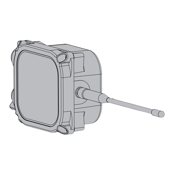
ISD Component Installation Connecting Cables To The Transmitter Connecting Cables To The Transmitter Note: The dip switches in each transmitter must be set to the proper dip switch settings listed in Appendix C. If the dip switches are set incorrectly, this device will fail to operate properly. 1. - Page 45 ISD Component Installation Connecting Cables To The Transmitter PROBE BATTERY 964-42.eps Figure 30. Wiring the Transmitter LEGEND FOR NUMBERED BOXES IN Figure 30 1. Green LED – Unit status. 6. Cable from battery or DC power source. 2. Red LED – Radio status. 7.
-
Page 46: Receiver Installation
ISD Component Installation Receiver Installation Receiver Installation 1. One Receiver is required per site and it is mounted in the vertical position (antenna up) on the outer wall of the same building housing the TLS RF. The Receiver is attached to its mounting bracket with #10 x 1/2” taptite screws from its install kit (see Figure 31). - Page 47 ISD Component Installation Receiver Installation 964-25.eps Figure 31. Attaching Mounting Bracket to Receiver or Repeater LEGEND FOR NUMBERED BOXES IN Figure 31 1. Receiver or Repeater 4. #10 x 1/2” taptite screws 2. 0.280” diameter hole (2) – mount this narrow side of bracket to wall or post 3.
- Page 48 ISD Component Installation Receiver Installation 964-26.eps Figure 32. Wiring the Receiver LEGEND FOR NUMBERED BOXES IN Figure 32 1. RS-485 Comm Activity - - These LEDs should always be flashing. Hand tighten both cable entry cord grip nuts to pre- There is no specific sequence.
-
Page 49: Repeater Installation
ISD Component Installation Repeater Installation Repeater Installation 1. Use of a single repeater is optional but may improve system performance when installed correctly. The Repeater should be located closer to the device transmitters to rebroadcast messages to the Receiver. Use the 15 Vdc power source provided in the Receiver to power the Repeater, or use a customer supplied non- interruptible, Class 2, 15 Vdc power source. - Page 50 ISD Component Installation Repeater Installation 964-27.eps Figure 33. Wiring the Repeater LEGEND FOR NUMBERED BOXES IN Figure 33 1. Red LED – on when power is applied. 6. S2 DIP switch 2. Green LED – Unit status 7. DC power input terminals - +15 Vdc and ground 3.
-
Page 51: Network Setup
Network Setup Hardware Overview An example TLS RF Wireless System site network illustrating a 32 Transmitter configuration is shown in Figure 34. The maximum number of Transmitters permissible in a site is 32 (requires 4 TLS RFs). Master 1 - 8 1 - 8 Aux 1 9 - 16... -
Page 52: Identifying Devices In The Tls Rf Wireless Site Network
Network Setup Identifying Devices in the TLS RF Wireless Site Network Identifying Devices in the TLS RF Wireless Site Network The Site ID must be identical for all Transmitters, the Repeater, and the Receiver in the site’s wireless network. Each Transmitter in the site’s wireless network must have a unique Device Number (from 1 – 32). Each TLS RF in the site’s network must have a unique Device Number (Master at 0 and Auxiliaries at1, 2, and/or 3). -
Page 53: Tls Rf Device Number
Network Setup Entering Device Numbers for the Site Network Each of the transmit interval selections selected by S2 settings are shown below for transmitters connected to probes and transmitters connected to mag sump sensors. Enter this number by setting DIP switches 1 – 4 on S2 (see Figure 30 on page 40) in the ‘Off’... -
Page 54: Entering The Site Id Number
Network Setup Entering the Site ID Number S2 DIP switch Settings Transmitter TLS RF Device Device Number TLS RF Number Master AUX 1 9-16 17-24 AUX 2 AUX 3 25-32 964-48.eps Entering the Site ID Number All of the site’s Transmitters, Repeater and Receiver must have the same Site ID number (0 – 15) entered in S2 DIP switches 5 - 8 (see settings below). -
Page 55: Site Startup Procedure
Network Setup Site Startup Procedure Site Startup Procedure Depending on the site layout, it is permissible to install RF devices in a variety of locations including dispensers and containment sumps. After all the wireless equipment has been installed, follow the steps below to verify the final setup. -
Page 56: Tls-450Plus Consoles
Diagnostics TLS-450PLUS Consoles BATTERY DIAGNOSTICS The battery status for wireless sensors is reported as Full, Medium, Low or Replace. • Full: greater than or equal to 3.4 Volts • Medium Range: 3.2V to 3.4 Volts • Low range: 3.0V to 3.2V •... -
Page 57: Alarms
Diagnostics TLS-450PLUS Consoles Figure 37. Example Vapor Valve Battery Status Printout When the wireless device battery reports a status ‘Replace’ continuously for 24 hours, a wireless device warning will be posted on the TLS to alert the operator that the battery requires replacement. The warning will persist in the TLS until the battery reports ‘Medium’... -
Page 58: Tls-350 Consoles
Diagnostics TLS-350 Consoles There is an additional alarm, Battery Status, when wireless equipment is used in place of direct wiring. The ISD, PMC and wireless device warnings and alarms are the same. If a warning or alarm condition occurs as a result of a failure in the wireless communication hardware, the system displays the communication failure for the affected wireless device. -
Page 59: Alarms
Diagnostics TLS-350 Consoles DIAGNOSTIC MODE PRESS <FUNCTION> TO CONT SMARTSENSOR DIAGNOSTIC - - - - - - - - - - - - DEC 13, 2010 12:15 PM SMARTSENSOR DIAGNOSTIC s 1:VRRM No. 1 PRESS <STEP> TO CONTINUE AIR FLOW METER SERIAL NUMBER 3001401 BATTERY:... -
Page 60: Background Information On Tls Rf Wireless System
Background Information On TLS RF Wireless System Antenna Propagation Basics The Veeder-Root TLS RF Wireless System site consists of one Server (Receiver) and one or more Client units (Transmitters) and uses the Frequency Hopping Spread Spectrum (FHSS) method of signal transmission in which each transceiver is programmed to follow a set of channels called the ‘Hopset’. -
Page 61: Interference
Background Information On TLS RF Wireless System RF Device Troubleshooting line of sight is impossible, e.g., transmitters are on opposite sides of the building, a Repeater should be installed that is positioned at a point that is both visible from the Transmitter and from the Receiver. The Repeater to Transmitter(s) signal path is much more significant than the Repeater to Receiver path. -
Page 62: Dev Column
Background Information On TLS RF Wireless System RF Device Troubleshooting 2. Open a serial communications program, such as HyperTerminal (available in Windows under Start\Programs\Accessories\Communications). Set the comm port settings to: 9600 Baud, 8 data bits, no parity, 1 stop bit. 3. -
Page 63: No_Data
Background Information On TLS RF Wireless System RF Device Troubleshooting NO_DATA Fuel/Water data is transmitted at different rates depending on activity and power-up/service switch status. The maximum transmission period is 2 minutes, the minimum 8 seconds. Temperature does not have to be read as often as fuel/water data. It is transmitted once every 2 minutes along with the fuel/water data. -
Page 64: Tls-Rf Wireless Troubleshooting
Background Information On TLS RF Wireless System TLS-RF Wireless Troubleshooting TLS-RF Wireless Troubleshooting Possible reasons for not receiving data from a device are: • Dead battery • Defective transmitter • Incorrect addressing on transmitter • Two devices with the same address •... -
Page 65: Multiple Or All Devices Out
Background Information On TLS RF Wireless System TLS-RF Wireless Troubleshooting MULTIPLE OR ALL DEVICES OUT TLS-RF 1. Locate the 5 LEDs on the left side of the main board in the TLS-RF. (Refer to Figure 12). The red LED (item 3) indicates power. -
Page 66: Appendix A: Site Survey For Wireless Probes
Appendix A: Site Survey for Wireless Probes OBJECTIVE The objective of the site survey are: • To acquire information that will ensure that all the items necessary to complete the installation are ordered and supplied. • To establish where the system assemblies will be best located, so that this information can be passed on to the installation team. -
Page 67: Key Information
Appendix A: Site Survey for Wireless Probes Key Information METHOD Take all details and measurements necessary to complete the site survey. The form has to be completed in the same format by all surveyors. This is so that when our orders are placed with the local distributor, the administrator will understand clearly the information on the survey and will be able to compile an accurate parts list. - Page 68 Appendix A: Site Survey for Wireless Probes Key Information • If double walled, does it have a leak monitoring device fitted • State whether the tank is direct fill or offset fill • State the approximate age of the tank MANHOLE CHAMBER INFORMATION •...
- Page 69 Appendix A: Site Survey for Wireless Probes Sketches • The RS-485 cable (Belden #3107A or equiv.) connecting the Receiver to the TLS RF console must be less than 250 feet. • Avoid placing Receiver near fluorescent lighting (min. 1 foot) or other source of electrical interference. TLS RF W2 CONSOLE LOCATION You should choose a suitable location for the TLS RF console, this would normally be within close proximity to the TLS console, with consideration given to the following guidelines:...
-
Page 70: Appendix B: Regulatory Information
MODIFICATIONS The FCC requires the user to be notified that any changes or modifications made to this device that are not expressly approved by Veeder-Root Company may void the authority to operate the equipment. CABLES Connections to this device must be made with shielded cables with metallic RFI/EMI connector hoods in order to maintain compliance with FCC Rules and Regulations. -
Page 71: System Specifications
Because of the type of batteries used in TLS RF Wireless 2 System (W2), follow local regulations regarding the safe disposal of the battery. Consult Appendix D of this manual for more information on battery disposal. -
Page 72: Appendix C: Device Dip Switch Settings
Appendix C: Device DIP Switch Settings TLS RF Number Settings The Dip Switch Locations to set the unique Device Number for the TLS RF(s) are shown in the Figure C-1. The TLS RF that monitors the Receiver and Transmitter Device Numbers 1 - 8 is considered the site’s master TLS RF and must have its Device Number set to 0 (default). -
Page 73: Transmitter/Receiver/Repeater Dip Switch Settings
Appendix C: Device DIP Switch Settings Transmitter/Receiver/Repeater DIP Switch Settings Transmitter/Receiver/Repeater DIP Switch Settings DIP switch locations for the Transmitter, Receiver and Repeater are shown in Figure C-2. Settings for these switches are listed in Figure C-3 through Figure C-6. TRANSMITTER RECEIVER PWR GND... - Page 74 Appendix C: Device DIP Switch Settings Transmitter/Receiver/Repeater DIP Switch Settings All Wireless 2 (W2) Transmitters S1: Positions Function Enable Transmitter c-3.eps Figure C-3. Transmitter Enable Settings - S1 All Wireless 2 (W2) Transmitters S1: Positions TRANSMITTER Device Num ber 1 (Master TLS-RF Device 1) Master TLS RF Connects to 2 (Master TLS-RF Device 2)
- Page 75 Appendix C: Device DIP Switch Settings Transmitter/Receiver/Repeater DIP Switch Settings Wireless 2 (W2) Mag Probe, Mag-XL & Mag Flex Probes Transm itter Interval in Seconds S2: Positions No Change (Idle) Fall (Dispense) Rise (Delivery) Read - TX Read - TX Read - TX 8 - 128 8 - 32...
- Page 76 Appendix C: Device DIP Switch Settings Transmitter/Receiver/Repeater DIP Switch Settings Wireless 2 (W2) Vapor Flowmeter S2: Positions Transm itter Interval in Seconds Read c-9.eps = Required settings Figure C-9. Vapor Flow Meter Transmitter Interval Settings - S2 Wireless 2 (W2) Transmitters, Receiver and Repeater (All Site ID settings must be the same) S2: Positions TRANSMITTER...
-
Page 77: Appendix D: Lithium Battery Safety Data
Appendix D: Lithium Battery Safety Data This appendix contains the manufacturer supplied Transportation Certificate and Material Safety Data Sheet for the lithium batteries used in the TLS RF Wireless 2 (W2) System. Lithium Battery Disposal Considerations 1. Waste disposal must be in accordance with the applicable regulations. 2. - Page 79 Material/Product Safety Data Sheet (MSDS-PSDS) LS/LSG/LSH/LST/LSX Lithium/Thionyl chloride products single cells and multi-cell battery packs Revision 8 Date 10/2008 1. Identification of the Substance or Preparation and Company Product Primary Lithium/Thionyl chloride unit cells and multi-cell battery packs (Li-SOCl Production Saft Ltd.
- Page 80 Aluminum chloride R14, R22, R37, R41, R43. anhydrous 1-5% 7446-70-0 S2, S8, S22, S24, S26, (AlCl S36, S45 Carbon 3-4% 1333-86-4 NONE KNOWN Amount varies depending on cell size. 4. First Aid Measures Remove from exposure, rest and keep warm. Inhalation In severe cases obtain medical attention.
- Page 81 7. Handling and Storage Do not crush, pierce, short (+) and (-) battery terminals with conductive (i.e. metal) goods. Do not directly heat or solder. Do not throw into fire. Handling Do not mix batteries of different types and brands. Do not mix new and used batteries.
- Page 82 10. Stability and Reactivity Product is stable under conditions described in Section 7. Heat above 100°C (150°C for the LSH 20-150 cells and the battery packs Conditions to avoid. assembled from them) or incinerate. Deform. Mutilate. Crush. Pierce. Disassemble Recharge. Short circuit. Expose over a long period to humid conditions. Materials to avoid Oxidising agents, alkalis, water.
- Page 83 14. Transport Information For the single cell batteries and multi-cell battery packs that are non-restricted to transport (non-assigned to the Miscellaneous Class 9), use lithium batteries inside label. Label for conveyance For the single cell batteries and multi-cell battery packs which are restricted to transport (assigned to Class 9), use Class 9 Miscellaneous Dangerous Goods and UN Identification Number labels.
- Page 84 Keep out of reach of children. S8 S22 Keep away from moisture. Aluminum S24 S26 Do not breathe dust. chloride Avoid contact with skin. anhydrous In case of contact with eyes, rinse immediately with (AlCl plenty of water. Wear suitable protective clothing. Classified under CHIP regulatory references 16.
Need help?
Do you have a question about the TLS RF Wireless 2 System and is the answer not in the manual?
Questions and answers