Table of Contents
Advertisement
Quick Links
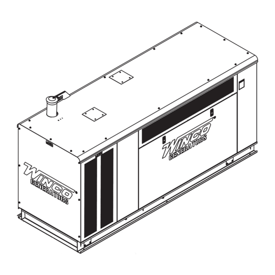
PSS90P4-XX/3
GENERATOR
INSTALLATION AND
OPERATORS MANUAL
COPY YOUR MODEL AND SERIAL NUMBER HERE
No other WINCO generator has the same serial number as yours.
If you should ever need to contact us on this unit, it will help us to
respond to your needs faster.
MODEL __________________________________________________
16200-016
SERIAL NUMBER _________________________________________
PURCHASE DATE _________________________________________
DEALER NAME ___________________________________________
DEALER PHONE # ________________________________________
www.wincogen.com
Advertisement
Table of Contents

Related Manuals for Winco PSS90P4 3 Series


Summary of Contents for Winco PSS90P4 3 Series
- Page 1 OPERATORS MANUAL COPY YOUR MODEL AND SERIAL NUMBER HERE No other WINCO generator has the same serial number as yours. If you should ever need to contact us on this unit, it will help us to respond to your needs faster.
-
Page 2: Table Of Contents
TABLE OF CONTENTS SAVE THESE INSTRUCTIONS SAFETY INFORMATION ANSI SAFETY DEFINITIONS SPECIFICATIONS INTRODUCTION TESTING POLICY PRODUCT DESCRIPTION PREPARING THE UNIT START-UP CHECK LIST UNPACKING INSTALLATION ENGINE-GENERATOR SET MOUNTING FUEL INSTALLATION INSTALLING THE FUEL LINE LIQUID PROPANE VAPOR (LP) NATURAL GAS (NG) FUEL PRESSURE FUEL PRESSURE TABLES NG/LP FUEL CONVERSION... -
Page 3: Save These Instructions
Should you experience a problem please follow the “Troubleshooting Tables” near the end of this manual. The warranty listed in the manual describes what you can expect from WINCO should you need service assistance in the future. OPM-185/A... -
Page 4: Safety Information
SAFETY INFORMATION This engine generator set has been designed and set or fuel tank. manufactured to allow safe, reliable performance. Poor D. Keep a fire extinguisher nearby and know its proper maintenance, improper or careless use can result in use. Fire extinguishers rated ABC by NFPA are potentially deadly hazards;... -
Page 5: Specifications
SPECIFICATIONS LP Gas Wattage 80,000 80,000 80,000 80,000 Volts 120/240 120/208 120/240 277/480 Phase Single Three Three Three Amps CB Size Hertz Natural Gas Wattage 90,000 90,000 90,000 90,000 Volts 120/240 120/208 120/240 277/480 Phase Single Three Three Three Amps CB Size Hertz Engine... -
Page 6: Introduction
INTRODUCTION MINIMUM TESTING POLICY UNIT VOLTAGE ATS AMPERAGE PSS60-3 120/240 Before any generator is shipped from the factory, it is fully PSS60-4 120/208 checked for performance. The generator is loaded to its PSS60-17 120/240 full capacity, and the voltage, current, and frequency are PSS60-18 277/480 carefully checked. -
Page 7: Preparing The Unit
A Start-Up Completion & Warranty Validation Form was sent along with this manual. This must be completed and returned to WINCO Inc. within 180 days of the factory invoice date. If this form is not returned, the Warranty may be voided. -
Page 8: Installation
INSTALLATION your local fire marshal, gas supplier or building inspector. WARNING Before proceeding with installation, be sure the operation WARNING: FIRE HAZARD selector switch is in the stop position and the battery All fuel runs should be installed by a licensed fuel supplier. disconnected. -
Page 9: Natural Gas (Ng)
Feet* Size of pipe WARNING: PERSONAL DANGER Do not use galvanized pipe in fuel line runs. The Up to 25 ft 1.25” pipe galvanized coating can become eroded and flake off, Over 25 ft** Use a two regulator system causing possible obstructions in the regulator or fuel *Allow an additional 3 feet for each standard elbow. -
Page 10: Fuel Pressure Tables
NG/LP FUEL CONVERSION The following diagram is of a natural gas (NG) installation. This generator set was tested on both LP and NG at the factory. Ensure proper fuel configuration before operating. CAUTION: EQUIPMENT DAMAGE Do not make any fuel adjustments or governor adjustments until all pressure readings are in compliance with specification. -
Page 11: Installing The Battery
INSTALLING THE BATTERY CAUTION WARNING In the following battery installation procedure, check to be The electrolyte is a diluted sulfuric acid that is harmful to sure the selector switch remains in the ‘off’ position. This the skin and eyes. It is electrically conductive and corrosive, should be your last step before initial start-up. -
Page 12: Connecting The Battery Charger & Block Heater
CAUTION: EQUIPMENT DAMAGE NEVER JUMP START these units. Doing so will destroy the engine control module, rendering the unit non- operational. Remove and fully recharge the battery before attempting to start. CONNECTING THE BATTERY CHARGER & BLOCK HEATER A three-stage battery charger is provided standard for all 12 volt standby systems. -
Page 13: Grounding
AC ELECTRICAL CONNECTIONS NOTICE: Wire Temperature Rating CLASS 1 WIRING METHODS ARE TO BE USED FOR ALL Cu Conductor Al Conductor FIELD WIRING CONNECTIONS TO TERMINAL OF A CLASS Volts 75°C 90°C 75°C 90°C 2 CIRCUIT. 120/240 WARNING 120/208 4/0 AWG A mainline circuit breaker has been provided inside the generator housing. -
Page 14: Mounting The Ats
MOUNTING THE ATS See the ASCO installation manual for additional details on proper wiring of the Automatic Transfer Switch. Because of the many different types of service, feeder, and distribution equipment, no specific wiring instructions can be provided. It is recommended that only copper wire be used. -
Page 15: Dc Electrical Interconnection
DC ELECTRICAL INTERCONNECTION DC INTERCONNECTIONS TO ATS CAUTION Never run the AC and DC wiring on the same conduit. Two control wires are required between the ATS panel and the generator control terminal box. Depending on the NOTE: There are various DC connectors on the engine distance, 14 and 16 gauge stranded wire should be used. -
Page 16: Initial Start Up
INITIAL START UP If you have the proper voltage at the generator the next step is to check the voltage at the generator terminals in WARNING: EQUIPMENT DAMAGE: the Automatic Transfer Switch. The voltage between the Before attempting to start this unit, complete your pre- G1 and the G3 terminals should be the same as it was start checklist and ensure the generator mainline circuit on the generator front panel. -
Page 17: Starting Procedure
STARTING PROCEDURE VOLTAGE REGULATOR WIRING CONTROL LAYOUT AS440 Automatic Voltage Regulator The following is a list of connections on the AVR. These have been factory set and other than voltage adjustment, should never be changed. STOP/RESET - This button places the module into its Stop/ Reset mode. -
Page 18: Automatic Transfer Switch
PREVENTATIVE MAINTENANCE MAINTENANCE SCHEDULE Reasonable care in preventative maintenance will ensure high reliability and a long life for the engine-generator set and Automatic Transfer Switch. SERVICE INTERVALS Check Engine Oil Level Daily WARNING: Check Coolant Level and for Leakage Daily When performing any type of maintenance on this Change Engine Oil and Filter Every 250 hrs... -
Page 19: Troubleshooting Tables
TROUBLESHOOTING TABLES UNIT WILL NOT 1. Digital genset controller not in “AUTO” CRANK WHEN THE 2. Transfer control switch not in “AUTOMATIC”. POWER FAILS 3. Incorrect wiring between transfer switch and generator. 4. Loose or dirty battery terminals. 5. Defective engine control module. 6. -
Page 20: Ac Wiring
THREE PHASE AC WIRING HIGH AND LOW WYE HIGH AND LOW WYE AC WIRING THREE PHASE-HIGH WYE THREE PHASE-LOW WYE THREE PHASE-HIGH WYE 277/480 VOLTS THREE PHASE-LOW WYE 120/208 VOLTS 277/480 VOLTS 120/208 VOLTS THREE PHASE - HIGH WYE 277/480V THREE PHASE - LOW WYE 120/208V THREE PHASE AC SINGLE PHASE AC... -
Page 21: Dse 7310 Mkii Wiring Diagram
DSE 7310 MKII WIRING DIAGRAM OPM-185/A... - Page 22 Air cooled units purchased for stock have 1 year to be sold. The warranty to the original retail customer commences on the date of sale of the product to them. All liquid cooled units have 180 days from the Winco invoice to submit a start up date. If no startup form is submitted, then warranty period starts on the Winco invoice date unit was sold.
- Page 23 Note 2: 3rd Year warranty coverage is parts only/no labor. Note 3: Round trip mileage is limited to 200 miles per trip and a total of 2 trips per repair unless authorized in writing by the WINCO Service Dept.
- Page 24 225 S. CORDOVA AVE • LE CENTER, MN 56057 Sales: 507-357-6821• sales@wincogen.com Service: 507-357-6831 • service@wincogen.com www.wincogen.com OPM-185/A...
Need help?
Do you have a question about the PSS90P4 3 Series and is the answer not in the manual?
Questions and answers