Table of Contents
Advertisement
Quick Links
INSTALLATION AND
OPERATORS MANUAL
COPY YOUR MODEL AND SERIAL NUMBER HERE
No other WINCO generator has the same serial number as yours.
If you should ever need to contact us on this unit, it will help us to
respond to your needs faster.
MODEL __________________________________________________
SERIAL NUMBER _________________________________________
PURCHASE DATE _________________________________________
DEALER NAME ___________________________________________
DEALER PHONE # ________________________________________
www.wincogen.com
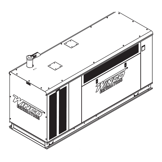
PSS40R4-2
PSS45R4-2
GENERATOR
Advertisement
Table of Contents

Related Manuals for Winco PSS40R4-2


Summary of Contents for Winco PSS40R4-2
- Page 1 OPERATORS MANUAL COPY YOUR MODEL AND SERIAL NUMBER HERE No other WINCO generator has the same serial number as yours. If you should ever need to contact us on this unit, it will help us to respond to your needs faster.
-
Page 2: Table Of Contents
“Troubleshooting Tables” near the end of this manual. The warranty listed in the manual describes what you can INSTALLING THE FUEL LINE expect from WINCO should you need service assistance in LIQUID PROPANE VAPOR (LP) the future. NATURAL GAS (NG) -
Page 3: Safety
SAFETY WARNING: FIRE HAZARD IMPORTANT SAFETY INSTRUCTIONS This engine generator set has been designed and Gasoline and other fuels present a hazard of possible manufactured to allow safe, reliable performance. Poor explosion and/or fire. maintenance, improper or careless use can result in A. -
Page 4: Specifications
SPECIFICATIONS PSS40R4 PSS45R4 LP Gas LP Gas Wattage 40,000 40,000 40,000 40,000 40,000 Wattage 40,000 40,000 40,000 40,000 40,000 Volts 120/240 120/208 120/240 277/480 346/600 Volts 120/240 120/208 120/240 277/480 346/600 Phase Single Three Three Three Three Phase Single Three Three Three Three... -
Page 5: Introduction
INTRODUCTION TESTING POLICY ENGINE/GENERATOR The engine generator set consists of an Origin 4.3L, industrial, four cylinder, liquid cooled engine equipped to Before any generator is shipped from the factory, it is fully run on liquid propane and natural gas. The engine operates checked for performance. -
Page 6: Preparing The Unit
1. As you receive your unit, it is critical to check it for any damage. If any damage is noted, it is easiest to refuse the shipment and let WINCO take care of the freight claim. If you sign for the unit, the transfer of the ownership requires that you file the freight claim 2. -
Page 7: Installation
INSTALLATION FUEL INSTALLATION The max ambient temperature is 122°F. For derating information, see specification sheet. This unit should be installed in a well ventilated area, ensuring the exhaust air The fuel supply should be as close as possible to the cannot be recirculated back into the engine. -
Page 8: Natural Gas (Ng)
size of 3/4 to 1 inch is generally adequate for distances up Feet* Size of pipe to 300 feet from the primary to the low pressure regulator. Up to 25 ft 1.25” pipe Consult your local fuel supplier for your exact requirements. The appropriate line size from the following table is then Over 25 ft* 1.25”... -
Page 9: Ng/Lp Fuel Conversion
NG/LP FUEL CONVERSION This generator set was tested on both LP and NG at the factory. Ensure proper fuel configuration before operating. CAUTION: EQUIPMENT DAMAGE Do not make any fuel adjustments or governor adjustments until all pressure readings are in compliance with specification. -
Page 10: Installing The Battery
INSTALLING THE BATTERY CAUTION WARNING In the following battery installation procedure, check to The electrolyte is a diluted sulfuric acid that is harmful be sure the selector switch remains in the ‘off’ position. to the skin and eyes. It is electrically conductive and This should be your last step before initial start-up. -
Page 11: Battery Charger & Block Heater
BATTERY CHARGER & BLOCK HEATER BATTERY CHARGER A three-stage, on-board marine battery charger is provided standard on this unit. The charger is a 5 amp dual use maintainer and charger designed to keep your batteries fully charged by maintaining them automatically. Make sure all DC battery connections are tight and clean. -
Page 12: Ac Electrical Connections
AC ELECTRICAL CONNECTIONS The following table shows the minimum conductor sizes NOTICE: CLASS 1 WIRING METHODS ARE TO BE USED between the generator and the ATS, based on wire type FOR ALL FIELD WIRING CONNECTIONS TO TERMINAL OF and temperature rating. Wire has been derated 40° C A CLASS 2 CIRCUIT. -
Page 13: Grounding
GROUNDING A grounding lug has been provided on the engine generator set. Check your local codes for proper grounding requirements. MOUNTING THE ATS See the ASCO installation manual for additional details on proper wiring of the Automatic Transfer Switch. Because of the many different types of service, feeder, and distribution equipment, no specific wiring instructions can be provided. -
Page 14: Dc Electrical Interconnection
DC ELECTRICAL INTERCONNECTION DC INTERCONNECTIONS TO ATS CAUTION Never run the AC and DC wiring on the same conduit. Two control wires are required between the ATS panel and the generator control terminal box. Depending on the NOTE: There are various DC connectors on the engine distance, 14 and 16 gauge stranded wire should be used. -
Page 15: Starting Procedure
F-153 Pre-Start & Warranty Form was sent with your generator. This form must be filled out by an Authorized WINCO Service Center and submit it to our WINCO Service Department for your warranty to become valid. After completing the checklist, the engine-generator set is ready for initial start-up. - Page 16 approximate voltage should be found between terminals G3 and G-N (120 volts AC). On three phase panels the G2 voltage level should also be checked. ON 240 VOLT (DELTA) SYSTEMS BE SURE YOU KNOW WHERE THE HIGH VOLTAGE “WILD” LEG IS. IT MUST BE IN THE SAME LOCATION ON THE LINE SIDE AS IT IS ON THE GENERATOR SIDE.
-
Page 17: Voltage Regulator
VOLTAGE REGULATOR The following is a list of connections on the AVR. These have been factory set and other than voltage adjustment, should never be changed. AS440 AVR AS540 AVR 1. VOLTS - Adjust generator output voltage. 1. VOLTS - Adjust generator output voltage. Clockwise to increase voltage. -
Page 18: Preventative Maintenance
PREVENTATIVE MAINTENANCE MAINTENANCE SCHEDULE Reasonable care in preventative maintenance will ensure high reliability and a long life for the engine-generator set and Automatic Transfer Switch. DAILY Check Engine Oil Level/Replenish if Needed WARNING: Check Coolant Level/Replenish if Needed When performing any type of maintenance on this Check for Fluid Leaks &... -
Page 19: Troubleshooting Tables
TROUBLESHOOTING TABLES UNIT WILL NOT 1. Digital genset controller not in “AUTO” CRANK WHEN THE 2. Transfer control switch not in “AUTOMATIC”. POWER FAILS 3. Incorrect wiring between transfer switch and generator. 4. Loose or dirty battery terminals. 5. Defective engine control module. 6. -
Page 20: Ac Wiring
WIRING - 4 LEAD WIRING - DELTA WIRING - 4 LEAD WIRING - DELTA AC WIRING SINGLE PHASE THREE PHASE -DELTA SINGLE PHASE THREE PHASE -DELTA 120/240 VOLTS 120/240 VOLTS SINGLE PHASE 120/240V THREE PHASE DELTA 120/240V 120/240 VOLTS 120/240 VOLTS E AC WIRING THREE PHASE AC W WYE... -
Page 21: Dse 7310 Mkii Wiring Diagram
DSE 7310 MKII WIRING DIAGRAM OPM-183/A... -
Page 22: Limited Warranty
Air cooled units purchased for stock have 1 year to be sold. The warranty to the original retail customer commences on the date of sale of the product to them. All liquid cooled units have 180 days from the Winco invoice to submit a start up date. If no startup form is submitted, then warranty period starts on the Winco invoice date unit was sold. - Page 23 Note 2: 3rd Year warranty coverage is parts only/no labor. Note 3: Round trip mileage is limited to 200 miles per trip and a total of 2 trips per repair unless authorized in writing by the WINCO Service Dept.
- Page 24 225 S. CORDOVA AVE • LE CENTER, MN 56057 Sales: 507-357-6821• sales@wincogen.com Service: 507-357-6831 • service@wincogen.com www.wincogen.com OPM-183/A...
Need help?
Do you have a question about the PSS40R4-2 and is the answer not in the manual?
Questions and answers