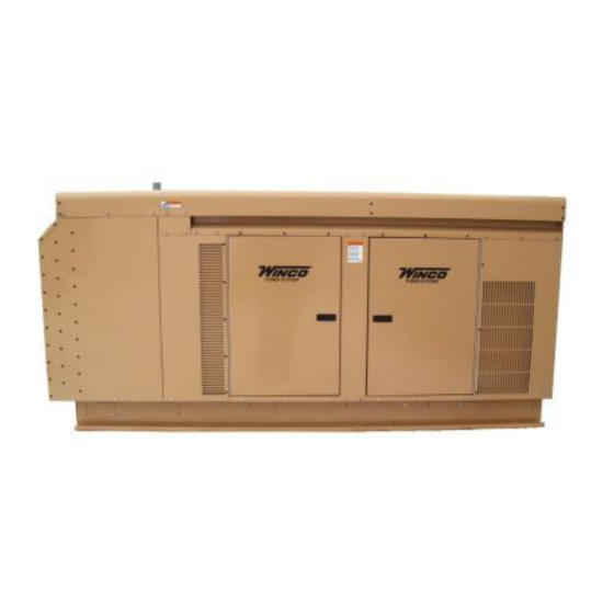
Summary of Contents for Winco PSS50LS
- Page 1 PACKAGE STANDBY SYSTEMS PSS50LS/C INSTALLATION AND PSS75LS/A OPERATIONS MANUAL for UNITS EQUIPPED WTH BASLER DIGITAL GENSET CONTROLS Engine Generator Set 225 SOUTH CORDOVA AVE LE CENTER MN 56057 507-357-6831...
-
Page 2: Table Of Contents
HERE DC Electrical Connections TRANSFER SWITCH INSTALLATION (UL) AC Electrical Connections No other WINCO generator has the same serial number as DC Electrical Connections yours. It is important that you record the number and other INITIAL START-UP vital information here. If you should ever need to contact us EXERCISER CLOCK on this unit it will help us to respond to your needs faster. -
Page 3: Guide To Product Safety
SAFETY INFORMATION FIRE HAZARD - Natural gas and L.P. present a hazard of possible explosion and/or fire. This engine generator set has been designed and manu- Do not smoke or use open flame near the generator factured to allow safe, reliable performance. Poor maintenance, set. -
Page 4: Basic Information
2) ENGINE/GENERATOR Before any generator is shipped from the factory, it is fully PSS50LS- The engine generator set consists of a GM 5.7L V-8 checked for performance. The generator is loaded to its full industrial, liquid cooled engine equipped to run on L.P./N.G. fuel. -
Page 5: Specification Table
If it should become necessary to change the 1% for each 10 degrees Fahrenheit above 60 degrees Fahren- baseline setting programmed into this controller please contact heit. the WINCO Inc. Service Department at 507-357-6831 for assistance. 3113-00 60706-156... -
Page 6: Preparing The Unit
UNPACKING INSTRUCTIONS ***** CAUTION **** EQUIPMENT DAMAGE - These units must be mounted on a ** NOTICE ** solid concrete pad to prevent air from exiting under the unit. When unpacking the generator set, be sure to inspect it carefully Allowing air to exit under the unit may cause the unit to overheat for freight loss or damage. -
Page 7: Fuel Line Installation
7-11 in 4-6 oz 4-6oz up to 25 feet* over 25 feet* STARTING TANK PSI 10-15 lbs 7-11 in 7-11 in PSS50LS 1" pipe not recommended 4-6 oz 4-6 oz PSS75LS 1" pipe use a two regulator system NO LOAD... -
Page 8: Lp Liquid Withdrawal
“stop” position. MOUNTING THE AUTOMATIC TRANSFER SWITCH (WINCO Non-UL only) A customer supplied twelve-volt BCI group 24 battery rated 650 CCA (minimum) is required to complete the installation. Install The automatic transfer switch (A.T.S.) connects the load (lights,... -
Page 9: Ac Electrical Connections
PSS50LS - The Automatic Transfer Switch typically shipped with “GENERATOR - G1, G2, G3 and G-N. The “hot” leads G1 G2 the PSS50LS system has a 230 Amp line side contactor installed and G3 wire directly to the generator side contactor, terminals to handle your normal power needs and a 230 Amp generator G1, G2 and G3. -
Page 10: Dc Electrical Connections
Automatic Transfer distribution equipment, no specific wiring instructions can be Switches will vary. The WINCO engine generator sets require a provided. It is recommended that only copper wire be used. In relay closure between Battery Negative (wire S1) and Start ( wire all cases it is essential that while the load is connected to the S23) to operate. -
Page 11: Initial Start-Up
***** WARNING ***** WARNING: ************* If you are not utilizing a WINCO non UL A.T.S. panel, STOP EQUIPMENT DAMAGE - DO NOT jump start these engine here and refer to the manual received with the switch panel generator sets. Starting these units on a low battery or jump for the proper initial start up procedure. -
Page 12: Exerciser Clock
clean 'break before make' action in the transfer switch. With the "Hour" and "Minute" buttons, select the time you The restoration of line power also sends a stop signal to the want the engine to stop. It is recommended you let the engine engine generator set. -
Page 13: Lp/Ng Conversion
AC short in generator components. (NG). If it should be necessary to change the type of fuel used after a unit is received, you will need to contact the WINCO ATS PANEL WILL NOT TRANSFER TO EMERGENCY Service Department at 507-357-6831. The same thing holds true... -
Page 14: 277/480 Volt
3113-00 Page 12 60706-156... -
Page 15: 120/240 Volt
3113-00 60706-156 Page 13... -
Page 16: Voltage Regulator Wiring
VOLTAGE REGULATOR WIRING THREE PHASE AND SINGLE PHASE 3113-00 Page 14 60706-156... -
Page 17: Dc Schematic - Wiring Diagram
3113-00 60706-156 Page 15... -
Page 18: Outline Drawing
3113-00 Page 16 60706-156... -
Page 19: Month Warranty
WINCO’s sole liability, and Purchaser’s sole remedy for a failure under this warranty, shall be limited to the repair of the product. At WINCO’s option, material found to be defective in material or workmanship under normal use and service will be repaired or replaced. For warranty service, return the product within 12 months from the date of purchase, transportation charges prepaid, to your nearest WINCO Authorized Service Center or to WINCO, Inc. - Page 20 225 SOUTH CORDOVA AVE LE CENTER MN 56057 Phone - 507-357-6831 Fax - 507-357-4857 60706-156-3113-00 Website www:wincogen.com...


Need help?
Do you have a question about the PSS50LS and is the answer not in the manual?
Questions and answers