Advertisement
All numerical values are in metric units [with U.S. customary units in brackets]. Dimensions are in
millimeters. Unless otherwise specified, dimensions have a tolerance of ±0.13 and angles have a
tolerance of ±2°. Figures and illustrations are for identification only and are not drawn to scale.
HIGH-VOLTAGE - MORTAL DANGER
•
This connector is intended for use in high-voltage applications. Special care must be applied
to ensure that the connector functions as intended.
•
If you suspect that the connector has been modified, damaged, contaminated, or otherwise
compromised, please discontinue its use immediately.
•
This connector should only be serviced by a trained and qualified technician.
1.
INTRODUCTION
This specification covers the requirements for assembly and mating/un-mating of the HC-STAK25 XE Header.
These high-voltage connectors must NOT be mated with any other type of connector.
When corresponding with TE Connectivity Personnel, use the terminology provided on this specification to help
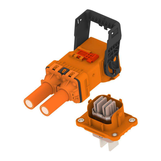
facilitate your inquiry for information. Basic terms and features of components are provided in Figure 1.
© 2024 TE Connectivity Ltd. family of companies.
All Rights Reserved.
*Trademark
TE Connectivity, TE connectivity (logo), and TE (logo) are trademarks. Other logos, product, and/or company names may be trademarks of their respective owners.
Instruction Sheet
HC-STAK25-2phi XE High voltage Connector
Figure 1: Exploded View HC-STAK25-XE HEADER
PRODUCT INFORMATION 1800-522-6752
408-160054
10JAN2024 REV A1
This controlled document is subject to change.
For latest revision and Regional Customer Service,
visit our website at www.te.com.
1 of 19
Advertisement
Table of Contents

Related Manuals for TE Connectivity HC-STAK25-2phi XE


Summary of Contents for TE Connectivity HC-STAK25-2phi XE
- Page 1 All Rights Reserved. PRODUCT INFORMATION 1800-522-6752 For latest revision and Regional Customer Service, *Trademark visit our website at www.te.com. TE Connectivity, TE connectivity (logo), and TE (logo) are trademarks. Other logos, product, and/or company names may be trademarks of their respective owners.
-
Page 2: Reference Material
408-160054 REFERENCE MATERIAL 2.1. Revision Summary 1. Revision 1 - Initial release 2. Section 3.6 Step 5 details with figure updated, Under Section 3.7 added new Figure 10.1 with details. 3. No changes. 4. Added new section as 3.5 and the existing section numbers changed correspondingly. Under Section 3.7 Step 2 details updated with images and new step. - Page 3 408-160054 Table 1: TE Part numbers for cable assembly RECOMMENDED SUBCOMPONENTS Part Numbers Quantity DESCRIPTION 2843101-1 HC-STAK25 XE Header Assembly 2843102-1 HC-STAK25 XE Header Inner Assembly 2434378-1 Generation Y Terminal 2386146-7 HVIL Housing See the reference drawing C-2843100 for specific validated wire sizes and part numbers 3.
- Page 4 408-160054 3.6. Circuit Identification The terminal cavities are numbered on the outer housing of the connector at the wire entry end. Figure 3: Circuit Identification 3.7. Header Assembly Procedures The following procedures show the details of the cable assembly and insertion instructions into the plug subassembly.
- Page 5 408-160054 Step 2 1. In the orientation shown in Figure 5A, push the HVIL terminals into the HVIL Housing cavities until a tactile and audible “click” is felt and heard. Pull back slightly to confirm the terminal is latched into the primary locked position.
- Page 6 408-160054 Step 3 Assemble the HVIL assembly into the Header Inner sub-assembly as shown in Figure 6, until the audible “click” is felt and heard. Figure 6: HVIL assembly inserting to the Header Inner Housing assembly Step 4 In the orientation shown below Figure 7A, align poka-yoke slot on the inner housing, with the corresponding poka-yoke post on the header outer housing, push the header inner assembly into the header outer assembly until a tactile and audible “click”...
- Page 7 408-160054 Figure 7: Inner Header Assembly shown before locking & After Locking 7 of 19 Rev A1...
- Page 8 408-160054 Step 5 In the orientation shown in Figure 8A & 8C, push the tabs into the header cavities until a tactile and audible “click” is felt and heard. Pull back slightly to confirm the terminal is latched into the primary locked position. Inner housing front surface need to place over butting surface of arbor press while inserting the tabs to avoid damage to the outer housing and shield as shown in right side Figure.
- Page 9 408-160054 Figure 8C: Tabs in locked position Step 6 In the orientation shown in Figure 9, slide the Header TPA to the locked position (follow the arrow), until a tactile and audible “click” is felt and heard. Figure 9: Header TPA in locked position 9 of 19 Rev A1...
- Page 10 408-160054 3.8. Connector Application A. Header Mating on the Header Plate The following procedures provide steps to mate the high-voltage header assembly and the Battery Flange. Step 1 Align the header locating posts with locating holes on the device as shown in Figure 10A. The header keying features will not allow it to seat completely if not oriented properly, and the battery flange holes will be misaligned with the compression limiter holes as shown in Figure 10B.
- Page 11 408-160054 Positioning Header into device when Inner housing positioned later stages: Align the header locating posts with locating holes on the device and align Header Poka-Yoke ribs with Poka- Yoke slot of inner housing as shown in Figure 10C. Header cannot be positioned on the device interface if it is not oriented properly, and Inner housing cannot be assembled into the outer housing if its orientation is not proper as shown in Figure 10D.
- Page 12 408-160054 Step 2 Torque the four M5 screws (Figure 11). The Torque requirement is 6.2 Nm ± 25%. Torque specified above refers to Class 8.8 M5 fasteners as per ISO 898. Any deviations must be approved by TE engineering. Bolt - Bolt - Bolt - Bolt -...
- Page 13 408-160054 3.10. Keying Capability Keying for matching Plug Keying for device Interface connector CODE-A CODE-B CODE-C CODE-D CODE-E CODE-F Figure 13: Header Assembly Keying Capability 13 of 19 Rev A1...
-
Page 14: Connector Mating
408-160054 3.11. Connector Mating 1. If the assembly is shipped with the Lever and/or red Connector Position Assurance (CPA) in the closed position, first if necessary, actuate the CPA to the open position, then open the lever to the open position as shown in Figure 14. - Page 15 408-160054 2. Align the plug and header connectors as shown in Figure 15 Make sure that the lever is still in the fully open position prior to engagement with the mating header. Figure 15: Plug and Header Assemblies Aligned Holding the Plug connector body, push the harness connector onto the header assembly until the header lever pivots completely engage with the Lever cam follower as shown in Figure 16.
- Page 16 408-160054 Rotate the lever towards the connector body until it is completely in the closed position as shown in Figure 17. Figure 17: Lever Actuation from Open to Close Push the red CPA forward until it stops as shown in Figure 18. Figure 18: CPA Actuation from Open to Close Ensure that the cables are rigidly secured at harness tie-down points, and that each tie-down point is static relative to the header mounting surface.
- Page 17 408-160054 Figure 19B: Example of a stabilization component for applications requiring vibration harsher than USCAR-2 Vibration Class V1. 3.12. Connector Un-mating Push the red CPA forward until it stops as shown in Figure 20. Figure 20: CPA from Close to Open Rotate the lever away from the connector body until it is completely in the open position as shown in Figure 21.
- Page 18 408-160054 Holding the connector body, pull the plug until it is completely separated from the header as shown in Figure 22. Do not use the lever as a handle to pull the plug apart. Figure 22: Plug and Header Un-mate 3.13.
- Page 19 408-160054 3.14. Inspecting For the inspection, refer to the customer drawing numbers 2843100-C, 2843101-C, and 2843102-C. 3.15. Other The following table specifies the saleable loose parts. Table 2: TE Part Numbers for saleable loose parts RECOMMENDED SUBCOMPONENTS Part Numbers Quantity DESCRIPTION 2843101-1 HC-STAK25 XE Header Assembly...
Need help?
Do you have a question about the HC-STAK25-2phi XE and is the answer not in the manual?
Questions and answers