Advertisement
Quick Links
Tyco Electronics Corporation
300 Constitutional Drive
Menlo Park, CA 94025 USA
© 2005-2006 Tyco Electronics Corporation. All rights reserved.
1.0
Introduction
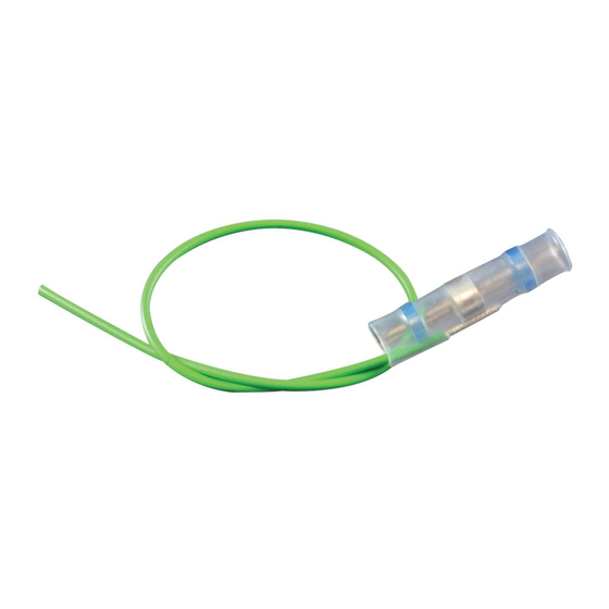
SolderSleeve one-step terminators provide electrical termination in a wide variety of
interconnect applications. One-step terminator capabilities include terminating wires to
component terminals, ground wires to cable shields, terminating coaxial cable, and wire-to-
wire splicing.
A precisely engineered, fluxed solder preform within the heat-shrinkable thermoplastic sleeve
provides a completely soldered, strain-relieved, encapsulated termination. The one-piece
design of one-step terminators simplifies installation, while their transparent insulation sleeves
make inspection easy.
2.0
Application Equipment
Equivalent tools may be used.
Steinel HL-1802E, HL1910
or HL2010 Hot-Air Gun
CV-5300 Hot-Air Gun
CV-5000 Thermogun
AA-400 Superheater
3.0
Part Selection, According to Application
Select correct part number from the SolderSleeve One-Step Wire and Cable Terminators
Selection Guide (H54335) or consult the technical data sheet (or Specification Control
Drawing) of the product (shield terminations, wire-to-wire splices, wire to component
terminals or for coax terminators).
4.0
Termination Procedure
Follow installation instructions carefully. Use adequate ventilation and
avoid charring or burning during installation. Charring or burning the
product will produce fumes that may cause eye, skin, nose and throat
irritation. Consult Material Safety Data Sheets RAY5103 (for CWT products)
and RAY5104 (for B-155 products) for further information.
Unless otherwise specified dimensions are in millimeters [Inches dimensions are in between brackets]
If this document is printed it becomes uncontrolled. Check for the latest revision.
SolderSleeve One-Step Wire and Cable Terminators
Installation Procedures for CWT and B-155 Products
IR-550 Mark II Infrared Heating Tool
MiniRay Infrared Heating Tool
Process Belt Heaters
Holding Fixture AD-1319
WARNING
No: RPIP-824-00
Rev: F
Date: April 28, 2006
Page: 1 of 11
Advertisement


Need help?
Do you have a question about the SolderSleeve CWT Series and is the answer not in the manual?
Questions and answers