Table of Contents
Advertisement
Quick Links
AMP+ Low-Medium Current Connector
Content
.......................................................................................................................................................
1.
2.
2.1
2.2
3.
4.
4.1
4.2
4.3
4.4
4.5
5.
6.
6.1
6.2
©2011 Tyco Electronics Corporation, a TE Connectivity Ltd. Company
All Rights Reserved
| Indicates Change
*Trademark.
logos, product and/or Company names may be trademarks of their respective owners.
Application
Specification
Document Class 1
HVA630-2phm V0
....................................................................................................................................
............................................................................................................
..........................................................................................................................
..................................................................................................................................
.........................................................................................................................
.................................................................................................................................
....................................................................................................................
.......................................................................................................................................
......................................................................................................................................
....................................................................................................................................
............................................................................................................. 16
............................................................................................................................ 17
..............................................................................................................................
.........................................................................................................................
TE Connectivity, TE connectivity (logo), and TE (logo) are trademarks.
114-101088
03JAN2010 Rev B1
2
2
2
3
4
4
4
5
6
7
15
17
17
1 of 19
Other
LOC AI
Advertisement
Table of Contents

Related Manuals for TE Connectivity HVA630


Summary of Contents for TE Connectivity HVA630
-
Page 1: Table Of Contents
©2011 Tyco Electronics Corporation, a TE Connectivity Ltd. Company All Rights Reserved | Indicates Change *Trademark. TE Connectivity, TE connectivity (logo), and TE (logo) are trademarks. Other LOC AI logos, product and/or Company names may be trademarks of their respective owners. -
Page 2: Scope
114-101088 SCOPE This specification describes the assembly of the 2 pos. HV Connector HVA630 2phm. This specification applies to hand-assembly of the coupling. PROCESSING NOTE The following technical documents, if referred to, are part of this specification. In case of a contradiction between this specification and the product drawing or this specification and the specified documentation then the product specification has priority. -
Page 3: General Documentation
114-101088 b) Specifications 108-101675 Product Specification HVA630-2phm 114-18388 Application Specification AMP MCP 6.3/4.8K Contact 109-18212 Shield and Insulation Crimp Validation for HV Applications General Documentation a) Cable specifications of prescribed cables Cross-section 2x4,0mm² Supplier: Coroplast Fritz Müller GmbH & Co. KG,... -
Page 4: Application Tools
APPLICATION TOOLS Required application tools Application device P/N: Description: AMP MCP 6.3/4.8K Contact (4-6mm²) See Application Specification 114-18388 Die Set, Locator HVA630-2phm, 4.0mm² 528041-9 Rev.C2 Shield crimp, 2pos. (2x4mm²) AT66 Die set adapter HV 541868-1 HV Crimping Machine, speed 10mm/sec 528008-4 Die Set, Locator HVA630-2phm, 6.0mm²... -
Page 5: Parts Of Assembly To Order
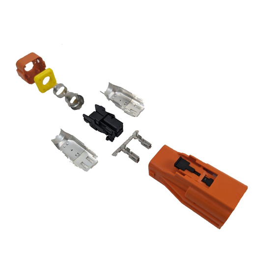
114-10108 Parts of Assembly to order Wire 2×4mm² 2×6mm² Part POS. QTY. Name PLUG HOUSING ASSY, CODE 2328732-X 2328732-X RECEPTACLE HOUSING ASSY 2328730-1 2328730-1 SHIELD CRIMP FERRULE, INNER 2332013-1 2332013-1 SHIELDING 2331718-1 2331718-1 OUTER CRIMP FERRULE 2332014-3 2332014-4 CABLE SEAL 2332016-3 2332016-4 COVER... -
Page 6: Security Advice
114-101088 Security Advice ATTENTION! - HIGH VOLTAGE APPLICATION - SHIELDING BRAID AND CABLE INSULATION MAY NOT BE DEMAGED! The assembly should only be performed by trained personnel. Avoid prolonged or repeated skin contact with shielding. (wear protective gloves) Rev B1 6 of 19... -
Page 7: Assembly Steps
114-101088 Assembly Steps Step 1 The following parts must be assembled in the following order on the cable (Figure 2). 1. COVER 2. CABLE SEAL 3. OUTER CRIMP FERRULE Figure 2 Step 2 Remove wire sheath material as shown: Remove outer sheath and foiled shielding according to determined length. (Figure 3) Shorten shielding braid and filler. - Page 8 114-101088 Figure 3 Step 3 Remove core insulation according to spec. 114-18388 (Figure 3) Crimp on all conductors AMP MCP 6.3/4.8K contact with the specified tool according to TE SPEC. 114-18388. Avoid twisting of the conductors. For easy insertion into RECEPTACLE HOUSING all should have the same orientation (Figure 4).
- Page 9 114-101088 Figure 5 Step 5 Insert the Contacts into the RECEPTACLE HOUSING (according to the cavity numbers shown in Figure 6) into their locking position. The contacts are locked when a click is heard on insertion. To ensure that the contacts are correctly inserted, push/pull with a force on the cables (max. 10N). After the contacts have been controlled for correct positioning and locking, the secondary lock of the RECEPTACLE HOUSING have to be locked (Figure 7).
- Page 10 114-101088 Figure 7 Note: If a dismounting of AMP MCP6.3/4.8K-contact is necessary use auxiliary tool according contact specification 114-18388. For opening the secondary locks use a flat screwdriver (e.g. 2.3x0.5) (Figure 8). If a secondary lock has been opened the RECEPTACLE HOUSING has to be exchanged.
- Page 11 114-101088 Step 6 Position the INNER CRIMP FERRULE next to the SCHIELDING BRAID (Figure 9). Slide first SHIELD on the RECEPTACLE HOUSING until it snaps on it (Figure 9). Figure 9 Slide second SHIELD on the RECEPTACLE HOUSING until it it stops (Figure 10). Figure 10 Position the INNER CRIMP FERRULE into the SHIELDS until it lies against the end of the SHIELDS (Figure 11).
- Page 12 114-101088 Figure 11 Step 7 Ensure that all parts are in the correct position (Figure 12). Ensure that the shield braids are homogeneous spread over the circumference of the crimp ferrule. Insert the Assembly into the Die Set with locator and crimp it. For correct handling and using of application tools see guideline 411- 18555.
- Page 13 114-101088 Figure 12 Cross section [mm] [mm] [mm] [mm] 2x4mm² 11,6 ± 0,15 max. 13,0 15,8 ± 0,15 max. 20 2x6mm² 13.0 ± 0,15 max. 14,6 Table 3 * Dim G = recommended inspection dimension against mistaken identity of outer crimp ferule * Rev B1 13 of 19...
- Page 14 114-101088 Step 8 Insert the Multicore Shielded Cable Assembly into the OUTER HOUSING ASSEMBLY. The Receptacle Housing ensures with its coding the correct polarisation in the Outer Housing Assembly (Figure 13). To ensure that the Cable Assy is correctly snapped in, pull with a force on the cable (max.
-
Page 15: End Of Line Test
114-101088 Press the COVER over the OUTER HOUSING. Ensure that both Catch-Mechanisms are snapped in. Figure 15 End of Line Test Assembled HV Connectors have to be tested electrically and mechanically to applicable requirements. On COVER are CONTROL OPENINGS for detecting existence of SEAL after COVER assembling. Figure 16 Rev B1 15 of 19... -
Page 16: Header Connector Mounting
114-101088 HEADER CONNECTOR MOUNTING Mounting header in correct orientation with the right coding to aggregate shown in following picture. Mounting screw Φ 5mm with Max screw head Φ 11.5mm,height 4mm,Min bearing area Φ 9.5mm. Screw type up to manufacturer, drill hole design according to screw type pretension Min 6000N,Max 6400N, Refer drawing 114-94037 note 10. -
Page 17: Connector Handling
114-101088 CONNECTOR HANDLING Plugging Connector - Push the plug fully until hearable snapping into the header - Verify that the connectors are fully locked with a light tug, do not pull on the wire. If the connection is not correct plugged, it will not be able to activate the CPA. - Push the CPA forward (see figure 19). - Page 18 114-101088 - Press the locking latch down to unlock the connector and pull the plug out of the header. Do not pull on the wire. (see figure 21) Figure 21 18 of 19 Rev B1...
- Page 19 E.JIANG 17SEP19 MODIFY COVER PN G.XU E.JIANG 03JAN20 SILVER XIONG 07JUN2018 TE Connectivity (Shanghai) Co., Ltd JESSE LI HEMS/Automotive 12JUN2018 CHINA 114-101088 EVAN JIANG 14JUN2018 APPLICATION SPECIFICATION for HVA630 2 POS. HV CONNECTOR V0 TITLE Rev B1 19 of 19...
Need help?
Do you have a question about the HVA630 and is the answer not in the manual?
Questions and answers