Advertisement
Quick Links
Installation Procedures for D-436-XX and D-200-XX
1.
Scope:
This document covers the installation procedures and inspection requirements for D-436-
XX and D-200-XX devices for making immersion-resistant crimped splices.
2.
References:
(1) MiniSeal™ Wire Splices Selection Guide (H50279 6/79).
(2) Tyco Electronics Customer Drawings (CD), D-436-XX.
(3) Tyco Electronics Customer Drawings (CD), D-200-XX
3.
Application Equipment and Tools:
3.1
Crimp Tools
(1) AD-1377 Crimp Tool.
(2) Manufacturer's recommended crimp tool for splices other than Tyco Electronics/
Raychem crimp splices.
3.2
Heating Tools
Products
D-436-XX
D-200-XX
D-436-XX,
D-200-XX
Note: CV-1981 Heating Tools are suitable alternatives. See product brochure for additional details.
4.
General Information:
4.1
Description
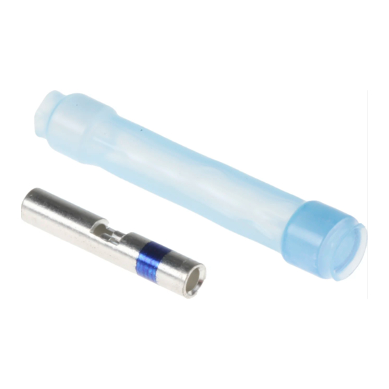
The parts covered by this document are designed for making immersion resistant crimped
splices in wires rated for at least 135C. This procedure covers crimp splices for making
_________________________________________
Unless otherwise specified dimensions are in millimeters. [Inches dimensions are in between brackets]
© 2007-2016 TE Connectivity Corporation. All rights reserved.
Raychem Devices
(Miniseal™) Sealed Crimp Splices
Heating Tool
AA-400 Superheater
HL1910E
HL2010E
AA-400 Superheater
HL1910E
HL2010E
IR-500 or IR-550
Infrared Heater
If this document is printed it becomes uncontrolled. Check for the latest revision.
No: RCPS-200-20
Rev: E1
Date: August 10, 2016
Reflector
Setting
Solder Sleeve
700°F (370°C)
PR-25D-
6 on dial
REFLECTOR
with HL-1802E-
ADAPT-PR or
700°F (370°C) on LCD
HL1802E-07616
REFLECTOR
Solder Sleeve
750°F (400°C)
PR-25D-
7 on dial
REFLECTOR
with HL-1802E-
ADAPT-PR or
750°F (400°C) on LCD
HL1802E-07616
REFLECTOR
RG-2
N/A
RG-6
(1)
(1)
(1)
(1)
Advertisement

Subscribe to Our Youtube Channel
Summary of Contents for TE Connectivity RAYCHEM D-436 Series
- Page 1 135C. This procedure covers crimp splices for making _________________________________________ Unless otherwise specified dimensions are in millimeters. [Inches dimensions are in between brackets] © 2007-2016 TE Connectivity Corporation. All rights reserved. If this document is printed it becomes uncontrolled. Check for the latest revision.
- Page 2 (2) One sealing sleeve with one integral multiple-hole seal and one separate multiple-hole seal (shown). _________________________________________ Unless otherwise specified dimensions are in millimeters. [Inches dimensions are in between brackets] © 2007-2016 TE Connectivity Corporation. All rights reserved. If this document is printed it becomes uncontrolled. Check for the latest revision.
- Page 3 7.9 - 8.7 mm (5/16 - 11/32 inch). _________________________________________ Unless otherwise specified dimensions are in millimeters. [Inches dimensions are in between brackets] © 2007-2016 TE Connectivity Corporation. All rights reserved. If this document is printed it becomes uncontrolled. Check for the latest revision.
- Page 4 (3) Center the sealing sleeve over the splice area as shown. _________________________________________ Unless otherwise specified dimensions are in millimeters. [Inches dimensions are in between brackets] © 2007-2016 TE Connectivity Corporation. All rights reserved. If this document is printed it becomes uncontrolled. Check for the latest revision.
- Page 5 Select proper slice components and prepare the wires as shown. (See 5.0.1, 5.0.2) _________________________________________ Unless otherwise specified dimensions are in millimeters. [Inches dimensions are in between brackets] © 2007-2016 TE Connectivity Corporation. All rights reserved. If this document is printed it becomes uncontrolled. Check for the latest revision.
- Page 6 (3) Center the sealing sleeve over the splice area as shown. _________________________________________ Unless otherwise specified dimensions are in millimeters. [Inches dimensions are in between brackets] © 2007-2016 TE Connectivity Corporation. All rights reserved. If this document is printed it becomes uncontrolled. Check for the latest revision.
- Page 7 _________________________________________ Unless otherwise specified dimensions are in millimeters. [Inches dimensions are in between brackets] © 2007-2016 TE Connectivity Corporation. All rights reserved. If this document is printed it becomes uncontrolled. Check for the latest revision.
- Page 8 _________________________________________ Unless otherwise specified dimensions are in millimeters. [Inches dimensions are in between brackets] © 2007-2016 TE Connectivity Corporation. All rights reserved. If this document is printed it becomes uncontrolled. Check for the latest revision.
- Page 9 The free end of a stub splice must be completely sealed. _________________________________________ Unless otherwise specified dimensions are in millimeters. [Inches dimensions are in between brackets] © 2007-2016 TE Connectivity Corporation. All rights reserved. If this document is printed it becomes uncontrolled. Check for the latest revision.
- Page 10 Then sealing sleeve is fully recovered _________________________________________ Unless otherwise specified dimensions are in millimeters. [Inches dimensions are in between brackets] © 2007-2016 TE Connectivity Corporation. All rights reserved. If this document is printed it becomes uncontrolled. Check for the latest revision.
- Page 11 Electronics be liable for any incidental, indirect, or consequential damages arising from the sale, resale, use or misuse of the product. _________________________________________ Unless otherwise specified dimensions are in millimeters. [Inches dimensions are in between brackets] © 2007-2016 TE Connectivity Corporation. All rights reserved. If this document is printed it becomes uncontrolled. Check for the latest revision.


Need help?
Do you have a question about the RAYCHEM D-436 Series and is the answer not in the manual?
Questions and answers