Table of Contents
Advertisement
Quick Links
© 2020 TE Connectivity family of companies
All Rights Reserved
*Trademark
TE Connectivity, TE connectivity (logo), and TE (logo) are trademarks. Other logos, product, and/or company names may be trademarks of their respective owners.
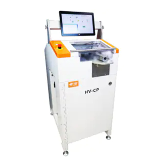
Semi-Automatic High Voltage Cable
Preparation Machine (PN 2335400-1)
SAFETY PRECAUTIONS - AVOID INJURY - READ THIS FIRST! ...................................... 2
1. INTRODUCTION .................................................................................................................. 4
2. SAFETY ................................................................................................................................ 4
Standards ....................................................................................................................... 5
Ear and Eye Protection .................................................................................................. 5
Safety Covers/Guards .................................................................................................... 5
Power Connections ........................................................................................................ 6
Safety Interlocks ............................................................................................................. 9
Emergency Stop (E-STOP) Switch .............................................................................. 11
3. DESCRIPTION ................................................................................................................... 12
Machine Overview ........................................................................................................ 12
Specifications ............................................................................................................... 12
Requirements ............................................................................................................... 13
Major Components ....................................................................................................... 14
Tooling ......................................................................................................................... 22
4. OPERATION ...................................................................................................................... 23
Overview ...................................................................................................................... 23
User Interface (UI) ........................................................................................................ 23
Initial Startup ................................................................................................................ 24
Processing ................................................................................................................... 26
5. MAINTENANCE ................................................................................................................. 39
Daily ............................................................................................................................. 39
Monthly ......................................................................................................................... 40
As-Needed ................................................................................................................... 40
Preventive .................................................................................................................... 44
6. TROUBLESHOOTING ....................................................................................................... 44
7. REPAIR AND REPLACEMENT ......................................................................................... 45
8. RECEIVING INSPECTION AND INSTALLATION ............................................................. 46
Receiving Inspection .................................................................................................... 46
Installation .................................................................................................................... 51
9. DECOMMISSIONING ......................................................................................................... 54
10. REVISION SUMMARY ....................................................................................................... 54
PRODUCT INFORMATION 1-800-522-6752
This controlled document is subject to change.
For latest revision and Regional Customer Service,
visit our website at www.te.com.
Customer Manual
409-35011
12 JUN 20
REV C
1 of 54
Advertisement
Table of Contents

Subscribe to Our Youtube Channel
Related Manuals for TE Connectivity HV-CP


Summary of Contents for TE Connectivity HV-CP
-
Page 1: Table Of Contents
1 of 54 All Rights Reserved For latest revision and Regional Customer Service, *Trademark visit our website at www.te.com. TE Connectivity, TE connectivity (logo), and TE (logo) are trademarks. Other logos, product, and/or company names may be trademarks of their respective owners. -
Page 2: Safety Precautions - Avoid Injury - Read This First
409-35011 SAFETY PRECAUTIONS — AVOID INJURY — READ THIS FIRST! Safeguards are designed into this application equipment to protect operators and maintenance personnel from most hazards during equipment operation. However, certain safety precautions must be taken by the operator and repair personnel to avoid personal injury, as well as damage to the equipment. For best results, application equipment must be operated in a dry, dust-free environment. - Page 3 409-35011 TOOLING ASSISTANCE CENTER CALL TOLL FREE 1-800-722-1111 (CONTINENTAL UNITED STATES AND PUERTO RICO ONLY) The Tooling Assistance Center offers a means of providing technical assistance when required. In addition, Field Service Specialists are available to provide assistance in the adjustment or repair of the application equipment when problems arise which your maintenance personnel are unable to correct.
-
Page 4: Introduction
1. The HV-CP is a semi-automatic, programmable, stand-alone machine designed to strip the cable jacket, braid, and dielectric foil from round, multi-layer cables in preparation for the application of crimped terminals. -
Page 5: Standards
Ear and Eye Protection Sound Level The following applies to the sound level produced by the HV-CP machine: The sound pressure levels at the operator position are at the infeed < 69.3 dBA, uncertainty K is 6.3 dBA. The sound power level is 74.0 dBA, uncertainty K, 7.4 dBA. -
Page 6: Power Connections
409-35011 Power Connections Main Electrical Power Disconnect The main electrical power disconnect switch is located on the left side of the machine. The switch may be locked in the “OFF” position,Lock Out/Tag Out (LOTO), to provide a safe condition for maintenance or repair by inserting a padlock (not included) into the locking locations (see Figure 4). - Page 7 409-35011 Pneumatic Connections 1. Pneumatic Power Disconnect A manually operated main air disconnect valve is located on the left side of the machine, below the main electrical power switch. The main air valve will exhaust all residual air from the machine when turned from the Supply (SUP) position to the Exhaust (EXH) position.
- Page 8 409-35011 2. Airlock Valve If the incoming air supply volume is inadequate, the cable grip force could be reduced during the vacuum cycle. The airlock valve is designed to improve the performance of the machine by maintaining the grip pressure at all times (see Figure 6). It also allows the cable grip to be released, if the guard door is opened and the red button on top of the airlock valve is depressed.
-
Page 9: Safety Interlocks
409-35011 Safety Interlocks The machine has two safety interlocks; one located under the sliding Top Guard at the front-left corner of the chassis (see Figure 7) and one located at the top-left inside corner of the Scrap Door (see Figure 8). Sliding door Interlock The interlock located under the sliding Top Guard (see Figure 7) is monitored by a dedicated safety relay. - Page 10 409-35011 Scrap door Interlock Interrupting the scrap door interlock (see Figure 8) does not cause the disabling of the servos or the dropping of air pressure but disables air to the vacuum system. CAUTION it is not advisable to open and/or empty the scrap bin while a cable prep cycle is in process. NOTE Resetting an interlock will not automatically re-start the machine.
-
Page 11: Emergency Stop (E-Stop) Switch
409-35011 Emergency Stop (E-STOP) Switch Description The Emergency Stop (E-STOP) switch is mounted on the top panel of the machine, in the lower left-hand corner (see Figure 9). Though it is clearly visible, an operator should purposely note the location and understand the operation of the E-STOP control in case of an emergency. -
Page 12: Description
Machine Overview Rotating Stripping Head The HV-CP is fitted with three blades, three cutting wheels and a mandrel. This offers many advantages, such as precision centering, braid flaring and matched toolsets for repeatable processing. The rotating blades cut the entire circumference of the insulation with precision. -
Page 13: Requirements
409-35011 Labeling The machine part number, serial number, manufacture date, and electrical specifications are provided on the label on the left side of the machine (see Figure 11). Figure 11 Requirements Electrical Requirements Voltage 200-265VAC Frequency 50/60Hz Circuit Single phase Current 10 Ampere Air Requirements... -
Page 14: Major Components
409-35011 Major Components Monitor The touch screen monitor is the key interface with the machine. The viewing angle can be adjusted (see Figure 13) by loosening the knobs on either side of the cross-bar, rotating the bar to suit and then tightening the knobs. - Page 15 409-35011 Gripper Holding the cable during the cycle, the gripper is a key part of the machine. Once the sequence is initiated, the actuator will bring the gripper jaws closer together (see Figure 14) until the cable is securely held. In response to the process parameters, the gripper will move the end of the cable to the correct location with respect to the blades and rollers.
- Page 16 409-35011 Cutting Mechanism The cutting mechanism is based on relative movement on plates controlled by pulleys and independent motors. The mechanism has two sets of cutting tools: the Contour Blades and the Cutting Wheels (see Figure 15). 1. Cutting Arms: Three arms on the rotating mechanism of the machine hold the contour blades and cutting wheels.
- Page 17 409-35011 Mandrel Providing support for the braid to be cut without affecting the inner insulation is the key function of the mandrel (see Figure 16). This component, like the Contour Blades and Cuttting Wheels, is sized specifically for each cable size and should be paired accordingly (see Section 3.5 for tooling). During a standard cycle, the mandrel will slide in between the braid and inner core to the appropriate depth.
- Page 18 409-35011 Cable Tunnel This feature of the machine ensures the cable is centered in the grippers during the cycle and directs the end of the cable to the cable sensor. It consists of left and right portions to direct the cable end fully (see Figure 18).
- Page 19 409-35011 Electrical Enclosure and Panels The electrical enclosure and panels (see Figure 20) contains all of the electrical components (servo motor drives, logic controllers, safety relays, etc.) for controlling the machine. DANGER There are no user-serviceable parts in the electrical enclosure. This door should not be opened by users - call field service for assistance.
- Page 20 409-35011 Utility Alcove On the left side panel of the machine, a recessed area (Utility Alcove) contains the Pneumatic Supply Assembly, Main Disconnect and Power cord, two USB 3.0 receptacles and one RJ-45 Connector. USB 3.0 Ports (2) RJ-45 Connector Main Disconnect and Power Cord Pneumatic...
- Page 21 409-35011 RJ-45 Connector The RJ-45 connection provides access to the Local Area Network (LAN) for MES (Manufacturing Execution System) connectivity. Instead of storing files on the local Linux computer, the machine transmits data over the ethernet using Message Queuing Telemetry Transport (MQTT), a publish-subscribe based messaging protocol. By implementing an MQTT message reader, a customer can have everything needed to track the process in many ways and permanently store that data for future reference.
-
Page 22: Tooling
409-35011 Tooling Instructions for a tooling change-over (different cable) or tooling replacement (worn or broken tooling) is presented in Section 6.3. Cutting wheels, contour blades, and mandrels are wear items. Customers should order several sets of tooling and keep them on hand at all times. Use Figure 23 to properly understand and choose the correct tooling from the table in Figure 24. -
Page 23: Operation
User Interface (UI) 1. The HV-CP monitor shows the software for creating different sequences on the HV-CP. The UI software for the HV-CP consists of two main screens, the Cable Builder screen (see Figure 25) and the Production Screen (see Figure 26). -
Page 24: Initial Startup
Production Screen 3. The production screen is where Articles are both created and run. This is the screen that will be most- used with operation of the HV-CP (see Figure 26). 4. Settings a. To expand tool bar in the UI, select the menu collapse arrow to expand the options. - Page 25 409-35011 User Access Configuration 1. To configure user access, expand the menu bar with the menu collapse arrow (see Figure 27), and select the control panel icon. Then select the Login/Logout icon from the control panel. Figure 27 2. User access based on the administrator (admin) and other “users” model. The administrator has authority to add new users and provide permissions for the user based on machine function (see Figure 28).
-
Page 26: Processing
409-35011 Processing Typically, day to day processing consists of some of or all the following operations: 1. Creating or recalling a Cable 2. Creating or recalling an Article 3. Revising a Cable 4. Revising an Article 5. Standard Operation or “Production” 6. - Page 27 409-35011 3. Once a cable has been created and used in an article it can be modified. The cable builder will then show a section of the screen to note the articles that it is used in (see Figure 29). NOTE A cable can be modified, but only if it is NOT used to define an article.
- Page 28 409-35011 4. Plug USB flash-drive into one of the machines USB ports located in the Utility Alcove (see Figure 31). Figure 31 28 of 54 Rev C...
- Page 29 409-35011 5. Select the File Name field and enter the name of your Article backup. NOTE After your new article name should be the file extension “.json”, this is something that must be entered manually (see Figure 32). 6. Select Save. NOTE A pop up window will appear informing the operator that the download was a success.
- Page 30 409-35011 7. To Import an Article from a USB flash-drive select “Import Article” from the Article Database Tab under Maintenance (see Figure 33). NOTE Make sure your USB flash-drive is plugged into one of the USB ports in the Utility Alcove before selecting “Import Article”. Figure 33 30 of 54 Rev C...
- Page 31 409-35011 8. Choose the Article you wish to upload from your USB flash-drive in the window (see Figure 34). 9. Select “Load”. NOTE A pop up window will appear informing the user that the upload was a success. Figure 34 31 of 54 Rev C...
- Page 32 409-35011 Creating an article From the production screen, navigate to the cable builder screen(see Figure 35). Create a New Article or Copy from an Existing Article (see Figure 35). Select the process type from the drop-down. Select the cable from the drop-down. It is recommended to copy from an existing article if there are parameters that are needed to be kept for future use.
- Page 33 NOTE The HV-CP is loaded with default cables and articles. It is possible to not have to create custom cables and articles. NOTE Because an article is the combination of a cable and user-input process parameters, it is ideal to create unique articles for each variety of product you want to make.
- Page 34 409-35011 CAUTION If you change the size of your tooling, you must change the article to match the tooling you want to calibrate. Otherwise, the machine will measure against the last selected article and will give you an error because the new tooling does not match the old article cable size.
- Page 35 409-35011 2. Above the “Mandrel Assembly” circled in Figure 36, the core diameter is displayed. This value is equal to the diameter of the inner insulation. 3. When selecting a mandrel assembly, rather than using the one that was automatically selected by the machine, the user can choose the one they need using the drop-down menu (see Figure 36).
- Page 36 Control panel Touching the Control Panel icon on the main menu screen (see Figure 36) brings up the control panel. The following control panel tools are to be used by the HV-CP administrator. 1. Language Icon To pick a language, touch the language icon, then select the appropriate language and save it.
- Page 37 NOTE Permissions are a method to allow or not allow individual users access to certain tasks or actions that can be performed on the HV-CP. With the user selected from the drop-down list, choose the appropriate radio button to provide the user permission for the various tasks and actions.
- Page 38 Figure 40 6. Networking The networking screen is used to allow the HV-CP to be configured on your LAN. Features of the HV-CP that require this functionality are the Manufacturing Execution System (MES), network time server and remote troubleshooting components. Please consult your Information Technology provider for details on configuring the HV-CP on your network.
-
Page 39: Maintenance
409-35011 8. E-STOP and RESET If there is a situation in which an emergency stop is required, the E-stop button on the front-left side of the machine should be pressed. To return the machine to the standard operation, twist the red knob in the direction of the posted arrows and press the reset switch. -
Page 40: Monthly
409-35011 Monthly Perform the following: Sliders (Door Counterweights): Clean and lubricate with NLGI#2 EP Grease. As-Needed Tooling Changeover DANGER When tightening or loosening any bolts on the face of the pulleys, it is possible that the mechanism will move. Use caution with hand placement when changing tooling. - Page 41 409-35011 3. Touch the “Home” button on the production screen (see Figure 42). 4. Touch the “Tooling Change” button. Tooling Change Button Home Button Figure 42 5. Insert tooling change tool, 2361560-1, in the hole (see figure 43). Tooling Change Tool Figure 43 41 of 54 Rev C...
- Page 42 409-35011 6. Contour Blades (see Figure 44) DANGER The Contour Blades are extremely sharp and should be handled with caution. a. To change the Contour Blades: (1) Bring the mandrel forward by pressing the tooling change button on the production screen. The machine will retract the wire clamp and cable sensor and move the mandrel to its most forward (outward) position.
- Page 43 409-35011 NOTE Cutting wheel can only be installed in one orientation. If cutting arm cap will not fit, check orientation of cutting wheel (see Figure 45). (7) Carefully install the Cutting Arm Cap onto the Cutting Arm. (8) Insert the (2) socket head cap screws and tighten securely. (9) Repeat for all 3 wheels.
-
Page 44: Preventive
(9) Perform the Calibration Cycle 9. Calibration Cycle: a. The HV-CP automatically calibrates the tooling to ensure the proper tooling set for the application are installed. b. To calibrate, press the button on the UI, and the machine will run the cycle. -
Page 45: Repair And Replacement
Connectivity Representative, or call 1-800-526-5142, or send a facsimile of your purchase order to 1-717-986- 7605, or write to: CUSTOMER SERVICE (038-035) TE CONNECTIVITY CORPORATION P.O. BOX 3608 HARRISBURG, PA 17105-3608 For machine repair service, contact a TE Representative at 1-800-526-5136. -
Page 46: Receiving Inspection And Installation
409-35011 8. RECEIVING INSPECTION AND INSTALLATION Receiving Inspection 1. The machine is thoroughly inspected during and after assembly. Before it is packed for shipment, a final series of tests and inspections are made to ensure proper functioning. 2. Once the machine is received at the facility of use, verify that as-received, the shipment looks like the image in Figure 49 (tooling, blades, mandrels, etc. - Page 47 409-35011 3. Uncrate the machine where there is enough light to permit a careful examination. a. Remove Heat Seal Bag and remove lag bolts holding Mounting Plates to pallet (4 places). b. Again, examine machine for any signs of damage from shipping and document observations. 4.
- Page 48 409-35011 (2) Remove tie-wraps holding the Top Guard in place (see Figure 52). Figure 52 (3) Remove plate securing a pin to one of the Cutting Arms (see Figure 53). Figure 53 48 of 54 Rev C...
- Page 49 409-35011 (4) Remove tie-wrap holding Wire Pull Actuator in place (see Figure 54). Figure 54 (5) Remove the tie-wrap holding the electrical enclosure key in place (place in a safe location) and the tie-wrap holding the main air disconnect valve in the LOTO position (see Figure 55). Figure 55 49 of 54 Rev C...
- Page 50 409-35011 (6) Remove tie-wrap holding Gripper jaws together (see Figure 56). Figure 56 (7) Remove tie-wraps holding the left and right Cable Gate Cylinder in fixed positions (see Figure 57 and Figure 58). Figure 57 50 of 54 Rev C...
-
Page 51: Installation
409-35011 Figure 58 c. Check all components to verify they are secure. d. Check all wiring for loose connections and for frayed or broken wires or insulation. e. Verify that all components and assembly/installation parts are accounted for against the Bill of Lading. - Page 52 409-35011 Machine air regulator Pneumatic lockout valve Main supply port Digital pressure switch Customer supplied quick disconnect Customer supplied airline Figure 59 3. Electrical Supply a. As show on the machine ID label (Fig. 11), the electrical supply must meet the following requirements: 200 to 265V AC, 50/60Hz, single phase (L-N or L-L), 10 Ampere.
- Page 53 409-35011 1.) Open Disconnect Enclosure as shown in Figure 61. STEP 3 Remove 2 Cover Screws and Remove Cover STEP 2 Remove 2 Faceplate Screws and Remove Faceplate STEP 1 Remove 1 Dial Screw and Remove Dial Figure 61 2.) Feed the power cord through the cable gland at the bottom of the Disconnect Enclosure. 3.) Connect line conductors to Main Disconnect Switch terminals as shown in Figure 62.
-
Page 54: Decommissioning
409-35011 9. DECOMMISSIONING A decommissioned machine should be returned to TE Connectivity for proper disposal. In compliance with the regulations in force in the country where the machine is used, the user must make sure that waste produced during operation is correctly disposed. Disposal of lubricants and parts removed must be carried out in compliance with the standards in force in the country where the tool is used 10.
Need help?
Do you have a question about the HV-CP and is the answer not in the manual?
Questions and answers