Table of Contents
Advertisement
Quick Links
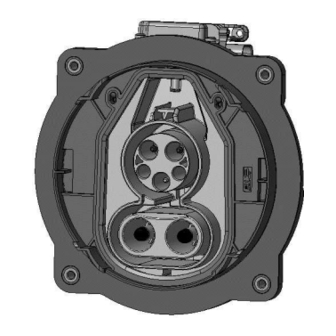
VEHICLE CHARGE INLET CCS1
acc. IEC62196-3 / SAE J1772
© 2020 TE Connectivity family of companies
All Rights Reserved
| Indicates Change
*Trademark. TE Connectivity, TE connectivity (logo), and TE (logo) are trademarks. Other logos, product, and/or company names may be trademarks of their respective owners.
Application
Specification
Class 1
114-94438 REV C1
18JUN2020
1 of 36
Advertisement
Table of Contents

Related Manuals for TE Connectivity CCS1


Summary of Contents for TE Connectivity CCS1
- Page 1 © 2020 TE Connectivity family of companies 1 of 36 All Rights Reserved | Indicates Change *Trademark. TE Connectivity, TE connectivity (logo), and TE (logo) are trademarks. Other logos, product, and/or company names may be trademarks of their respective owners.
-
Page 2: Table Of Contents
SCOPE ............................3 1.1. Content ..............................3 1.2. Processing Note ............................3 APPLICABLE DOCUMENTS ....................4 2.1. TE Connectivity Documents ........................4 WIRES............................5 3.1. Assessment of the wires ......................... 5 3.2. Wire selection ............................5 3.3. Wire preparation ............................5 3.4. -
Page 3: Scope
114-94438 REV C1 SCOPE 1.1. Content This specification describes the handling and assembly of the vehicle charge inlets CCS I acc. IEC 62196-3 for conductive charging of electric vehicles. This specification applies to manual assembly of the components from series production tooling, for the standard version. 1.2. -
Page 4: Applicable Documents
2.1. TE Connectivity Documents Drawings / Bill of material: See Customer drawing for COMBO 1 INLET DBAG basic number: A 000 340 78 00... -
Page 5: Wires
114-94438 REV C1 WIRES The following designations are used in this specification. The illustrations are exemplary and schematically. 3.1. Assessment of the wires To ensure the required electrical crimp contactability the permissible maximum storage period of 8 months for unprocessed cable (referring to cable manufacturer production date) must be respected. 3.2. -
Page 6: Application Tools
114-94438 REV C1 DC-HV-Cable : Cross-section 1 x 16,0mm² Supplier: Coroplast Outer Diameter 10,2 -0,6 Cable description: FHLR2GCB2G 16mm²/0.21 T180 0.6/0.9kV acc. LV216-2 Tab. A.2 Part No.: 9-2611 / 16mm² DC-HV-Cable : Cross-section 1 x 50mm² Supplier: Coroplast Outer Diameter 15,8 - 0,6 Cable description:... -
Page 7: Requirements On The Crimped Contact
114-94438 REV C1 REQUIREMENTS ON THE CRIMPED CONTACT 5.1. Terms of pin contact Figure 1 5.2. Conductor position The single strands of the conductor are clamped in the wire barrel (drill hole at crimp area). Sticking out or on top crimped single strands are not permitted. The wire end must be visible at the inspection hole before and after crimping. -
Page 8: Crimpposition
114-94438 REV C1 Measuring plane Figure 2 Crimp Die Sets are subject to wear and their condition and quality have to be monitored. Suspect and/or worn Die Sets have not to be used for the production of these crimps. Die Sets are available as spare parts. - Page 9 114-94438 REV C1 Contacts of wire diameter 16 mm² and 50mm² have to be crimped with crimping tool position at end of crimp area as shown. Figure 4 9 of 36...
-
Page 10: Cross Sections
114-94438 REV C1 5.5. Cross sections When creating cross sections, the correct grinding layer must be selected. The Grinding layer has to be at middle of crimp area and may not be inside of serration. Figure 5 5.6. Contact area During processing and following processing, the contact area may not be damaged or bended. -
Page 11: Measuring Equipment And Measuring Position
114-94438 REV C1 For 50 mm² meeting the specific shape and position tolerances shown at figure 7 must be ensured before the contact is inserted into the housing. Figure 7 Measuring the shape and position deviation is not always necessary. If the contact is obviously straight by eye a simplified shape and position functional test, at diameter 6mm², can be performed by inserting it into a suitable housing cavity (crimp may not scrape the walls of secondary lock). -
Page 12: Assembly Instructions
114-94438 REV C1 ASSEMBLY INSTRUCTIONS In this chapter the way of assembly is described. All pictures in this chapter may differ from the specific product. The pictures illustrate the way of assembly and may not reflect all variants. The exact appearance of the components can be seen in the drawing documentation. 6.1. -
Page 13: Parts To Order
114-94438 REV C1 6.2. Assembly configuration cable exit The inlet can be assembled with different cable exit directions.The required configaration can be chosen according to customer requirement. Configurations for cable exit AC 90° sidewards: Attention of symbol triangle and rectangle PE cable must be always in lower position Configurations for cable exit AC 20°... -
Page 14: Security Advice
114-94438 REV C1 6.4. Security Advice ATTENTION! - HIGH VOLTAGE APPLICATION - CABLE INSULATION MUST NOT BE DAMAGED! Figure 12 The assembly should only be performed by trained personnel. Avoid prolonged or repeated skin contact with silver plated contacts (wear protective gloves)! ATTENTION! ESD safety e ui ed- The p i ted i uid oa ds a e stati se siti e de i es, hi h a... -
Page 15: Assembly Steps
114-94438 REV C1 6.5. Assembly Steps Step 1 The COVER CABLE SEAL AC [Pos. 9], STRAIN RELIEF AC [Pos. 8] and FAMILY SEAL AC [Pos. 7] must be pushed over the signal wires, the ground wire and the AC-Multicore wire. Pay attention to place all wires at correct positions. - Page 16 114-94438 REV C1 Alternative to prepar cable according step 2 figure 15, is it also possible to prepare cable similar figure 16. In this case it is necessary to protect complete overlapping shield braid with tape (e.g. Certoplast 9mm). A marking on outer isolation in a distance “E” (or in an offset to “E”) to the cut off position is recommended to ensure the proper position of the outer isolation in the FAMILY SEAL AC [POS.7].
- Page 17 114-94438 REV C1 Step 3 Preparation of PE single wire. Dismantle PE-single wire cable acc. Figure 18. Figure 18 THE SINGLE BRAIDS MAY NOT BE CUT OR DAMAGED DURING DISMANTLE PROCESS. Position outer end of Variant of CABLE Removal of Wire Size COVER [POS.9] EXIT [POS.
- Page 18 114-94438 REV C1 Step 4 Dismantle LV single wires (dim. A) acc. spec. 114-13000. Crimp Contacts acc. Spec. 114-13000 on LV signal wires. THE SINGLE BRAIDS MAY NOT BE CUT OR DAMAGED DURING DISMANTLE PROCESS. Figure 20 Removal of Position outer end of Variant of CABLE EXIT Wire Size isolation...
- Page 19 114-94438 REV C1 Step 5 There are 3 different ways of preparation of DC-HV-Cables necessary: For DC-HV-Cables of 16mm² in combination with CABLE EXIT AC 90° SIDEWARDS please see Step 5a. For DV-HV-Cables of 50mm² in combination with CABLE EXIT AC 90° SIDEWARDS please see Step 5b. For DV-HV-Cables of 50mm²...
- Page 20 114-94438 REV C1 Table 8 Take care, to protect single conductors and braid against contamination, bending and other damages until crimping process. The COVER CABLE SEAL DC (Pos. 10) and FAMILY SEAL DC [Pos. 11] must be pushed over the DC-HV-wires (figure25) Figure 25 Crimp the conductors to the PIN DIA8.0 CONTACT [Pos.
- Page 21 114-94438 REV C1 Step 5b DC-HV-Cables of 50mm² in combination with CABLE EXIT AC 90° SIDEWARDS. THE SINGLE BRAIDS MAY NOT BE CUT OR DAMAGED DURING DISMANTLE PROCESS. Remove outer isolation and shielding-foil of DC-HV-Cable acc. dimension B (figure27). Remove inner isolation acc. dimension A (figure 27). Figure 27 Removal of outer Position outer end...
- Page 22 114-94438 REV C1 Processing OUTER FERRULE [16] The shielding braid must not be combed out. Fold back the shielding braid over the outer insulation of the cable. Push then the OUTER FERRULE [Pos. 16] over the shielding braid. Crimp OUTER FERRULE [Pos. 16]. The crimp quality has to be conform to TE Spec. 109-18212. The crimp height according table 10 has to be measured according Chapter 5.4 of TE Spec.
- Page 23 114-94438 REV C1 Crimp the conductors to the PIN DIA8.0 CONTACT [Pos. 12] with the specified tools. Care shall be taken that all braids are caught in the crimp. Not inserted braids may jeopardize HV requirements! Wires shall be completely inserted to be visible through the inspection hole (Figure 31). Figure 31 Crimp height H shall be conform to dimension acc.
- Page 24 114-94438 REV C1 Step 5c DC-HV-Cables of 50mm² in combination with CABLE EXIT AC 20° DOWN (STRAIGHT) THE SINGLE BRAIDS MAY NOT BE CUT OR DAMAGED DURING DISMANTLE PROCESS. Remove outer isolation and shielding braid of DC-HV-Cable acc. dimension B, remove inner isolation acc.
- Page 25 114-94438 REV C1 Crimp the conductors to the PIN DIA8.0 CONTACT [Pos. 12] with the specified tools. Care shall be taken that all braids are caught in the crimp. Not inserted braids may jeopardize HV requirements! Wires shall be completely inserted to be visible through the inspection hole (Figure 36). Crimp height H shall be conform to dimension acc.
- Page 26 114-94438 REV C1 26 of 36...
- Page 27 114-94438 REV C1 Step 7 Assemble the Radial Seal [Pos. 5] to the Cable Exit Cover [Pos. 6]. Radial Seal should be properly seated into the Collar of the Cable Exit Cover. Ensure also correct orientation of seal acc. figure 38. Figure 38 Step 8 Pass the SIGNAL CONNECTOR, AC POWER PINS and PE PIN through the AC slot and DC pins...
- Page 28 114-94438 REV C1 Step 9 Insert the Contacts from the rear side into the Inlet Housing (figure 40) according to the cavity description into their locking position. ATTENTION: The correct contact positions must be ensured BEFORE pushing the contacts into locking their cavities in locking position.
- Page 29 114-94438 REV C1 Step 10 After the contacts have been controlled for correct positioning and locking, both SECONDARY LOCKS have to be pushed upwards (figure 42). Ensure that all hooks are properly engaged with the inlet housing, which must be controlled by the double audible click and by visible inspection (figure 43). ATTENTION: The Pin position has to be ensured BEFORE locking the Secondary Lock! ESD safety required - The printed circuit boards are static sensitive devices, which can be damaged if touched without the necessary electrostatic discharge (ESD) precautions.
- Page 30 114-94438 REV C1 Step 11 Connect Micro Mate-N-Lok Connector to PCB-Header. Ensure that hook is properly engaged with the mating part in PCB (figure 44). ESD safety required - The printed circuit boards are static sensitive devices, which can be damaged if touched without the necessary electrostatic discharge (ESD) precautions.
- Page 31 114-94438 REV C1 Step 13 Move the STRAIN RELIEF AC [POS. 8] together with FAMILY SEAL AC [POS. 7] into their position in the CABLE EXIT [POS. 6]. Ensure that all wires (AC-Multicore, PE-Single wire, LV-wires) are well positioned in the FAMILY SEAL, so that the seal lips are placed on the outer isolation of the cables Ensure that the mark from Step 2 is on the same Level to the End of the CABLE EXIT [Pos.
- Page 32 114-94438 REV C1 Step 14 Assemble Protection Cap [Pos. 14] at Inlet Housing [Pos. 1] as shown in the Figure 48 Typical press-on-force = 10N; max. press-on-force = 100N. Protection Cap Figure 48 Step 15 Thread the service unlock ball wire through the hole in the actuator housing. Snap the ball into the seating of the red unlocking strap as shown in the figure 49.
- Page 33 114-94438 REV C1 Step 16 Assemble the Connector for the Actuator connection acc. to application spec of MQS-Connector. (Applicator 2151038; Die Set 5-1579001-1). Push connector on actuator housing. To ensure that the connector is correctly inserted, pull and push with a low force on the housing (max. 10N). Figure 50 Step 17 Apply a label on specified face of CABLE EXIT.
-
Page 34: End Of Line Test
114-94438 REV C1 6.6. End of Line Test The assembled Charge Inlet has to be tested electrically and mechanically to applicable requirements, including High Voltage test. As a minimum the following tests have to be performed: Isolation resistance: TEST VOLTAGE: 1000VDC Inspection Duration: 1s min. - Page 35 114-94438 REV C1 REVISION RECORD DATE FIRST REVISION FOR COMBO I ARAVIND H.M F. WITTROCK 11SEP2017 TABLE 1, FIGURE 6. REWORKED M. SCHMIDT F. WITTROCK 13OCT2017 ESD-SAFETY INFORMATION ADDED; RADIAL M. SCHMIDT F. WITTROCK 16APR2018 SEAL P/N CHANGED; PRESS FORCES DEFINED - GEN.4 VARIANTS AND 40A VARIANT ADDED;...
- Page 36 VERSUS DC SHIELD" ADDED -6.6 DIELECTRIC WITHSTAND VOLTAGE, -TEST VOLTAGE: 1500VAC WAS 2000VAC -"AC VERSUS AC; AC VERSUS MULTICORE SHIELD, DC+ VERSUS DC-; DC VERSUS DC SHIELD" ADDED ARAVIND H.M TE CONNECTIVITY GERMANY GMBH 11SEP2017 AMPÈRESTRAßE 12-14 D-64625 BENSHEIM GERMANY M. SCHMIDT 11SEP2017 F.
Need help?
Do you have a question about the CCS1 and is the answer not in the manual?
Questions and answers