
Related Manuals for VeEX FaultScout FL150


Summary of Contents for VeEX FaultScout FL150
- Page 1 FL150 FaultScout User Manual Optical Link Qualification Test Set P/N D07-00-161P RevA00...
- Page 2 Please direct all questions to your local VeEX® Sales Office, Representative, or Distributor. Or, contact VeEX tech- nical support at www.veexinc.com. No part of this user manual may be reproduced, translated into a foreign language, or be transmitted electronically without prior agreement and written consent of VeEX Incorporated as governed by International copyright laws.
-
Page 3: Table Of Contents
Front Panel Layout LED Indicators Keypad Quick Start Guide Screen Navigation Inserting the Fiber Preventing Inaccurate Readings Working with FL150 FaultScout Test Setup Test Parameters Other Parameters Thresholds Setup About Autosave Parameters Table of © VeEX Inc. All Rights Reserved. Contents... - Page 4 Using the Optical Light Source Visual Fault Locator (VFL) Using the VFL Fiber Scope The Importance of Fiber Connector Inspection Certifications and Declarations What is CE? RoHS ComplianceVeEX QUALITY AND ENVIRONMENTAL POLICY About VeEX Table of © VeEX Inc. All Rights Reserved. Contents...
- Page 5 Customer Care Table of © VeEX Inc. All Rights Reserved. Contents...
-
Page 6: General Information
VeEX Inc., and to use it solely as intended and described in this manual. The purchaser is prohibited from copying, reverse engineering, decompiling, or disassembling the software. ... -
Page 7: Warranty
For warranty information on VeEX Inc. products, go to www.veexinc.com. To activate the warranty, please register your production at www.veexinc.com/Support/ProductRegistration. Patent Information VeEX Inc. product hardware and software may be protected by one or more patents on file with the United States Patent Office. Documentation Conventions... -
Page 8: Safety Information
General Safety Guidelines NEVER use any other charger (e.g., for NiCd, NiMH, or Li-ion) other than the one supplied by VeEX to charge the Li-Po batteries in this product. Only use chargers designed for Lithium Polymer (Li-Po) batteries. -
Page 9: Lithium Polymer Battery Handling & Storage Advice
When storing batteries for extended periods, store at a half charged state. Optical Connectors The test sets display a laser warning icon when the laser source is active to alert the user about a potentially dangerous situation. It is recommended to: © VeEX Inc. All Rights Reserved. Safety Information... -
Page 10: Electrical Connectors
3. Never use a fiber microscope to check the optical connectors when the laser source is active. Electrical Connectors Telephone lines may carry dangerous voltage. Always connect the electrical test ports to known test interfaces which carry low level signals. Safety Information © VeEX Inc. All Rights Reserved. -
Page 11: Introduction To Fl150 Faultscout
(check with factory on availabilityand R-Server Advanced Management option is also available. Key Features Features are subject to change. For current product features and specifications, see the product data sheet at www.veexinc.com. Introduction to FL150 © VeEX Inc. All Rights Reserved. FaultScout... -
Page 12: Package Contents
Package Contents FL150 FaultScout test set Micro-USB male to USB-A male OTG dongle AC/DC adaptor Input: 100-240 VAC (50/60 Hz), 1.5A max Output: 12VDC Li-Polymer battery Carrying Case (PN: C01-00-013G) Introduction to FL150 © VeEX Inc. All Rights Reserved. FaultScout... -
Page 13: Theory Of Operation
The FL150 FaultScout PON meter has a single fixed SM SC/APC connector port designed to measure GPON 1490 nm and 10-GPON 1577 nm downstream signal power and perform fault location without the need to swap test ports. © VeEX Inc. All Rights Reserved. Theory of Operation... -
Page 14: Basic Operation
SPAN: Used to setup launch or receive fibers, default = NONE; Initial event loss is excluded in Total Link Loss Show Section Loss: Do not show dB/km between events in Event table view Auto Zoom: Expand link in viewing window to show start to end. Basic Operation © VeEX Inc. All Rights Reserved. - Page 15 Setup and additional tools such as FiberScope can be accessed by tapping the applicable System button and selecting the Tools options. For more details about System Settings, see the V150 Common Functions Manual on www.veexinc.com. System Setting – Utilities/Tools/Files Menu © VeEX Inc. All Rights Reserved. Basic Operation...
-
Page 16: Test Ports And Interfaces
Dust, dirt and pollution severely impact optical performance. Inspect/Clean connectors when excessive Loss or Reflectance/ORL is observed in measurements. In the Setup, activating Front Panel Check can alert you to abnormal connection to meter. Front Panel Layout FL150 Basic Operation © VeEX Inc. All Rights Reserved. - Page 17 Provides touch screen calibration if it can’t be accessed by GUI A+F Screen Capture function F Slider Button provides Page Scroll function Others: D Power ON and Battery Charge Indication LED E micro-B USB interface (includes USB-A OTG adapter cable) © VeEX Inc. All Rights Reserved. Basic Operation...
-
Page 18: Led Indicators
2. Select Setup and then select Auto ONT to Splitter, Splitter to ONT, PON (SPL1) or P2P for single pulse tests. Use V-Scout mode for multi-pulse tests. 3. Tap the pencil icon to edit test profiles. Check Front Panel Check or OPM Measurement, if desired. Basic Operation © VeEX Inc. All Rights Reserved. -
Page 19: Screen Navigation
Push the connector in and you will hear a click. Make sure the optical connector is inserted fully to guarantee good contact. © VeEX Inc. All Rights Reserved. Basic Operation... -
Page 20: Preventing Inaccurate Readings
If the optical fiber is not aligned properly and/or completely connected, it will cause serious loss and reflection. In addition, contaminated or damaged connectors can impact performance and result in false event detection. Basic Operation © VeEX Inc. All Rights Reserved. -
Page 21: Working With Fl150
FaultScout Fiber Menu FaultScout Test Setup Available wavelengths are displayed. FaultScout Setup Screen Test Parameters Select the Mode from the drop down menu: Manual, Auto, V-Scout, Manual Realtime, and Auto Realtime. © VeEX Inc. All Rights Reserved. Working with FL150... - Page 22 ONT is connected. PON (1Spl): Use this mode when testing ONT-OLT up to single 1x64 Splitter. (Connect at Customer site or FDP/FDT.) P2P: Use this mode for testing point-to-point fiber spans, not PON. Working with FL150 © VeEX Inc. All Rights Reserved.
-
Page 23: Other Parameters
Fiber Model RI (Refractive index, N): Setting for each available wavelength (also known as group index) is used to convert time to distance. Setting proper value (1.2000-1.8000) determines accurate distance measurement. © VeEX Inc. All Rights Reserved. Working with FL150... -
Page 24: Thresholds
Thresholds values can be set for each test wavelength. For PON testing, it is recommended to use G.697/G.98x P/F Threshold profile. Event Loss (splice, connectors, mux) and Reflectance threshold settings determine if a detected anomaly should be reported. Working with FL150 © VeEX Inc. All Rights Reserved. - Page 25 If needed, stop and clean connectors, or proceed with the bad connection. Mated APC connectors should not exceed -50dB Reflectance. OPM measurement: For dual PON 1490/1577nm, measure downstream signal before verifying drop fiber. © VeEX Inc. All Rights Reserved. Working with FL150...
-
Page 26: Setup About
Trace ID field be created and the start # entered in the Index field. Autosave Parameters - Fiber Auto Save: To enable/disable autosave result. Working with FL150 © VeEX Inc. All Rights Reserved. - Page 27 To change the value, click Fiber Index and select Force to enter a specific value or Reset to reset the counter. Autosave Parameters - Common The following information can be pre-set and automatically saved in the file. © VeEX Inc. All Rights Reserved. Working with FL150...
-
Page 28: View Setup
Autosave Results: To view or export a saved result, select the Results button. Files can be accessed by selecting Files Saved or USB in the Results menu. View Setup Tap the Display button to access the Display Settings screen and set display options. Display/Interface Settings Working with FL150 © VeEX Inc. All Rights Reserved. -
Page 29: Span Settings
Use the Span Settings to offset the length of an external launch fiber or patchcord, which is connected to the fiber under test; otherwise, it becomes part of the fiber span and analysis. The launch fiber can be offset or com- pensated in any of the following ways: © VeEX Inc. All Rights Reserved. Working with FL150... -
Page 30: Measure Cables
The same procedure for offsetting Launch Fibers applies to offsetting Receiver fibers which are often used in Fiber to The Antenna (FTTA) applications. Measure Cables Use the Measure button to measure the Launch/Receive cables and populate the result into the Length field automatically. To measure cable length: Working with FL150 © VeEX Inc. All Rights Reserved. -
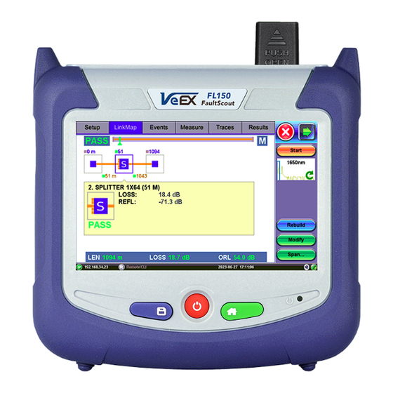
Page 31: Linkmap
After a FaultScout test is complete, a LinkMap will be displayed to provide details for all events found on the fiber that was tested. Below is an example of how a single splitter PON fiber might look. © VeEX Inc. All Rights Reserved. Working with FL150... -
Page 32: Events
1xN Splitter from the ONT (end-user) side Loss > 4dB, Reflectance not applicable ONT/ONU -30 dB < Reflectance < -40 dB LinkMap Icon Descriptions Events If a KNOWN event does not appear, try the following: Working with FL150 © VeEX Inc. All Rights Reserved. -
Page 33: Event Table
Use Up/Down arrows to navigate the event table and to display or move to the highlighted event. Use the green Left/Right arrows to move the marker between the start and end of fiber being tested. To maximize the Event table, select the cross symbol again. © VeEX Inc. All Rights Reserved. Working with FL150... -
Page 34: Event Types
The Event is color coded depending on Threshold settings defined in the test setup (see Thresholds). indicates the event fails or exceeds the Pass threshold criteria. Green indicates the event passes the Fail threshold criteria. Working with FL150 © VeEX Inc. All Rights Reserved. -
Page 35: Event Editing
2. Use the left/right arrows to highlight the event on the Event Table. Tap Event<Modify on the right sidebar. A marker with two small markers will appear on the trace. 3. When markers and measurement is performed, click the Accept button on the right sidebar. © VeEX Inc. All Rights Reserved. Working with FL150... -
Page 36: Measure
The Markers can be moved using the touchscreen or using side rocker button to move the Active Marker. The Markers display the following: Working with FL150 © VeEX Inc. All Rights Reserved. -
Page 37: Zoom/Scroll Controls
The parameters of the trace corresponding to the markers' position and measurement mode will be displayed at the bottom of the screen. Zoom/Scroll Controls Zooming operations are possible in both Events and Measure mode. Zoom Operations © VeEX Inc. All Rights Reserved. Working with FL150... -
Page 38: Distance Measurements
Distance measurement - measure expanded trace view The distance accuracy depends on the accuracy of optical fiber refraction index value setting. Loss Measurements Loss Modes - Several Loss modes are available for manual measurements depending on Working with FL150 © VeEX Inc. All Rights Reserved. - Page 39 Level difference in dB Attenuation based loss/distance When using Realtime test mode, use the 2-Point LSA method to stabilize loss values. To reduce noise, change Display Real Time Refresh Rate to Low. © VeEX Inc. All Rights Reserved. Working with FL150...
-
Page 40: Splice Loss Measurement
Reflectance is measured in -dB (negative decibels). A smaller negative value (-65dB) indicates a smaller reflec- tion whereas a larger negative value (-45dB) indicates a larger reflection. Larger reflectance will appear as a Working with FL150 © VeEX Inc. All Rights Reserved. -
Page 41: Orl Measurement
2. Select ORL from the drop-down list. 3. Place marker A at the beginning of the fiber under test and marker B at the end of the fiber span © VeEX Inc. All Rights Reserved. Working with FL150... - Page 42 ORL; moving marker B to less than the end will result in a change in ORL. The bottom of the screen displays: Distance to A cursor Distance to B cursor Distance between markers A-B Loss between the markers A-B (dB) Optical Return Loss (ORL), dB Working with FL150 © VeEX Inc. All Rights Reserved.
-
Page 43: Traces
Trace Information window to view all relevant information pertaining to the saved file: Device: OTDR supplier name, Mainframe ID and serial #, and optical module serial # (if applicable) © VeEX Inc. All Rights Reserved. Traces... - Page 44 Trace Information - Device General: Date/Time, Job ID, Cable ID, Fiber ID, Group ID, Fiber Type, Originating/Terminating locations, and Comments Trace Information - General Measurement: Test parameters used to make measurement. Traces © VeEX Inc. All Rights Reserved.
- Page 45 Trace Information - Thresholds For more information on Span settings and Launch/Receive cable offset, see "Span Settings" on page 29. Change the Refractive Index (RI) and Analysis Thresholds like Backscattering Co-efficient (BC) for the selected trace: © VeEX Inc. All Rights Reserved. Traces...
- Page 46 4. Tap OK to apply changes. All changes will be applied immediately. 5. After carefully noting the JobID/CableID/FiberID/TraceID fields, save the trace. The Job/C- able/Fiber/Trace determine the location to which the trace is saved. For multi-wavelengths/multi-pulsewidths, edit/change each trace separately. Traces © VeEX Inc. All Rights Reserved.
-
Page 47: Results
The JobID/CableID/FiberID/TraceID fields determine the location to which the trace is saved. If these set- tings are not set accurately, the trace will not save to the desired location. To save the current/active test: © VeEX Inc. All Rights Reserved. Results... -
Page 48: Third Party Viewers
When third party viewing is checked, the unit will save filtered .sor results so that third party software will dis- play any trace identical to how it appears on VeEX test sets. Once saved in using 3rd party format, unfiltered data cannot be viewed afterwards. - Page 49 © VeEX Inc. All Rights Reserved. Results...
-
Page 50: Optical Power Meter (Opm)
Zero: Recalibrates the meter zero value level. Recommended when measurement conditions change significantly. When in doubt, perform this procedure prior to making any measurements. For Optical Power Meter © VeEX Inc. All Rights Reserved. (OPM) - Page 51 Put the cover over the OPM test port BEFORE recalibrating. OPM server on: for factory use only Optical Power Meter © VeEX Inc. All Rights Reserved. (OPM)
-
Page 52: Optical Light Source (Ols)
CW (Continuous Wave): Select to continually measure level, loss, and reflectance in optical components. 270 Hz, 330 Hz, 1000 Hz, 2000 Hz (Pulse): Select this option to send intermittent light pulses. Optical Light Source © VeEX Inc. All Rights Reserved. (OLS) - Page 53 5. When testing is complete, tap Laser OFF to power off the OLS, and then disconnect the cable and replace the port cover. Optical Light Source © VeEX Inc. All Rights Reserved. (OLS)
-
Page 54: Visual Fault Locator (Vfl)
2. Power ON the unit, and then tap the X icon to close OTDR mode and display the Fiber Main Menu. 3. Tap Visual Fault Locator on the main menu. The Caution screen appears. Visual Fault Locator © VeEX Inc. All Rights Reserved. (VFL) - Page 55 (than continuous light). It can also be used with audible detectors (toners) that can identify faint light or in well-lit (bright) environments. 6. Tap Auto Off. When VFL application is exited, the VFL powers down automatically. Visual Fault Locator © VeEX Inc. All Rights Reserved. (VFL)
- Page 56 When not in use, disconnect the cord from the port, replace dust covers, and keep the port cap securely closed. VFL may not work with G.657 bend insensitive patchcords or cables with dark jacketing material or armored cables. Visual Fault Locator © VeEX Inc. All Rights Reserved. (VFL)
-
Page 57: Fiber Scope
DI-1000/DI-1000MPO/DI-3000 Digital Fiber Inspection Microscope Adapter Tips Guide. All wired fiber inspection scopes are powered via a USB Type-A connection with a host device or the VeEX Power Bank/WiFi Bridge. For host devices that have Micro-B or Micro-C input ports, USB Type A to Micro-B or Micro-C OTG dongle adapters are available as an add-on order from VeEX. - Page 58 Please ensure the correct fiber connector type is used before inserting it into the test port or connector. Mismatched connector types will damage the optical end faces and the test set. Refer to the V150 Common Functions User Manual on www.veexinc.com for more information. Fiber Scope © VeEX Inc. All Rights Reserved.
-
Page 59: Certifications And Declarations
Our quality and environmental policy is to limit and progressively eliminate the use of hazardous substances and chemicals in the design and manufacture of our products. VeEX products are classified as Monitoring and Control Instruments under Article 2, Section (1), Category 9 of the WEEE 2002/96/EC Directive. - Page 60 Additional RoHS substance restrictions for the Monitoring and Control Instruments were adopted by EU Dir- ective 2015/863 (March 31, 2015). These new restrictions will take effect from July 22, 2021. VeEX has estab- lished a program to ensure that from July 22, 2021, all its products to be sold and shipped into the EU market will conform with (EU) 2015/863.
-
Page 61: About Veex
With a blend of advanced technologies and vast technical expertise, VeEX products address all stages of network deploy- ment, maintenance, field service turn-up, and integrate service verification features across copper, fiber optics, CATV/DOCSIS, mobile 4G/5G backhaul and fronthaul, next generation transport network, Fibre Channel, car- rier &...
Need help?
Do you have a question about the FaultScout FL150 and is the answer not in the manual?
Questions and answers