Table of Contents
Advertisement
Quick Links
Advertisement
Table of Contents

Subscribe to Our Youtube Channel
Related Manuals for VeEX VePAL TX320s


Summary of Contents for VeEX VePAL TX320s
-
Page 2: Table Of Contents
Table of Contents 1.0 General Information 2.0 Safety Information 3.0 Introduction 3.1 Platform Overview 3.2 Front Panel 3.2.1 LED's 3.2.2 Key Pad 3.2.3 Touch Screen 3.3 Battery 3.3.1 Battery Overdraw Protection 3.4 Hardware Configurations 3.5 Home Screen 3.6 Quick Access Menu 4.0 Getting Started 4.1 Initial Settings 4.1.1 Change language and user interface style... - Page 3 5.1.6 Global Settings 5.1.7 Date and Time 5.1.8 Remote Access 5.1.9 EZ Remote 5.1.10 VF Noise Calibration (Microphone) 5.1.11 Maps Downloader 5.1.12 High Precision Clock Sources 5.2 Help 5.3 VeExpress 5.4 R-Server (Advanced Management) 5.5 Software Upgrade 6.0 File Manager 6.1 File Manager: Working with Saved Results, Profiles, Images 6.2 USB Memory Browser 6.3 Manage SD Card...
- Page 4 7.5.4 Data Card 7.5.5 WiFi inSSIDer 7.5.6 OTDR Viewer 7.5.7 GNSS Operation 7.5.8 GNSS Sky View 7.6 Web Browser 8.0 Certification and Declarations 9.0 About VeEX Go back to TOC TX300s_Platform_Manual_RevB01 Page 4 of 123...
-
Page 5: General Information
VeEX Inc., and to use it solely as intended and described in this manual. The purchaser is prohibited from copying, reverse engineering, decompiling, or disassembling the software. - Page 6 Go back to top Go back to TOC 1.3 Patent Information VeEX product hardware and software may be protected by one or more patents on file with the United States Patent Office. Go back to top Go back to TOC 1.4 Documentation Conventions...
-
Page 7: Safety Information
Do not operate the instrument in the presence of flammable gases or fumes or any other combustible environment. VeEX Inc. assumes no liability for the customer's failure to comply with safety precautions and requirements. - Page 8 50% of its capacity. Spare battery packs should be charged and used at least once a year to prevent over-discharge (rotate them regularly). It is recommended to charge and use battery packs at least every three months. Battery packs must not go without recharging (reconditioning) for more than six months.
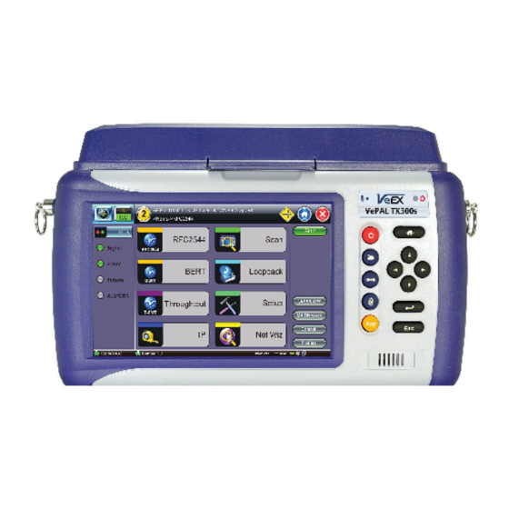
- Page 9 3.0 Introduction to TX300s Series ® VeEX TX300s series test sets are portable test solutions, with flexible configurations, for Core, Transport, Metro and Access Networks carrying Data, Voice, and Video. All-in-one hardware platform reduces CAPEX The VeExpress ecosystem allows users to Buy, Rent, Lease-to-own and share test feature licenses to optimize OPEX...
-
Page 10: Front Panel
3.1 TX300s Overview Go back to TOC 3.2 Front Panel 3.2.1 LEDs Power LED: A single LED indicates the power state of the unit. The LED is off when the unit is powered off. The LED is green when the unit is powered on. The LED is orange when the unit is connected to the AC Mains and powered off (charging). -
Page 11: Key Pad
3.2.2 Key pad Power: Press for 2 seconds to turn the test set ON or OFF (prevents accidental ON/OFF). Save Test Results: Saves the current Test Results with customized or auto naming (yyyymmdd-hhmmss format). The F1 key on standard keyboards can be used when controlled via VNC Clear History: Resets blinking LED reminders of past Errors or Alarms. -
Page 12: Battery Overdraw Protection
Attention! For safety reasons, the battery charging time is always limited to a maximum of three hours If the TX300s is being used while charging and a full charge (100% capacity) cannot be achieved within three hours, the charging will automatically stop. - Page 13 Configurable as Fully-Loaded Dual Port Group (Allows independent Dual Tests) Universal multi-service test modules offer OTN/SDH/SONET/PDH/DSn, Carrier Ethernet, MPLS, Fibre Channel, CPRI/OBSAI, Synchronization and more Additional Technologies, Rates and Test Features can be added later, via SW licenses One 300SM Module - Single Port Group Configurable as an economical Single Port Group (Single Test) Universal multi-service test module offers OTN/SDH/SONET/PDH/DSn, Carrier Ethernet, MPLS, Fibre Channel, CPRI/OBSAI, Synchronization and more...
- Page 14 CPRI/OBSAI, Synchronization and more Additional Technologies, Rates and Test Features can be added later, via SW licenses Perfect companion to the OTDR hardware option One 340SM Module - Single Port Group Flexible, all-in-one multi-service test solution, from 64kbps to 16 Gbps (can be combined with 100G and OTDR modules) Transport, Core, Metro, SAN, Backhaul and Fronthaul applications Supports up to four test port groups with independent and simultaneous measurements Test cards summary provides an overview of up to four running tests, as well as test application switching and management...
- Page 15 External clock interface 150 ppm clock offset generation Soft LED indicators OTDR Module Fiber Optics, Transport and Service Verification, Testing & Troubleshooting OTDR: Standard (+7dBm), High-power (+23 dBm) and PON (+23 dBm) versions OTDR, OPM and VFL ports with interchangeable optical bulkhead connectors This factory-installed option can be combined with any of the multi-service modules Go back to TOC TX300s_Platform_Manual_RevB01...
-
Page 16: Home Screen
3.5 Home Screen Go back to TOC 3.6 Quick Access Menu This multi-tasking section provides convenient and immediate access to system features, connectivity, accessories, results, etc. Those features are always available, independently of whether tests are running or not. TX300s_Platform_Manual_RevB01 Page 16 of 123... -
Page 17: Getting Started
4.0 Getting Started - TX300s 4.1 Initial Settings 4.1.1 Change language and user interface style Before using the platform, set the language and user interface style as needed. By default, the user interface style is set to USA if the unit is shipped to North America and to International if the unit is shipped to outside North America. International user interface style USA Interface style To change the GUI language and user interface style... -
Page 18: Launching Test Applications
4.2 Launching Test Applications The Test Cards summary/status screen offers intuitive test application management (launch, monitor, switching and release). Each test card is associated with a test module (orange numbers) and their individual test port groups (white numbers); capable of showing two, three or four possible tests, depending on the capabilities of the modules installed in the test platform. -
Page 19: Understanding Test Application Gui
2. Select the Technology Group. 3. Select the desired Test Mode based on the application to be tested. 4. Tap on the OK button to confirm. The test port group is assigned to the selected test application. Required software/firmware is loaded. Go back to TOC 4.3 Understanding Test Application GUI A. -
Page 20: Utilities
5.0 Utilities 5.1 Platform Settings This section provides settings for the global parameters of the test set or platform (system settings). Settings Menu Go back to TOC 5.1.1 About This section provides information about the software version, serial number, and MAC address of the management port of the unit, as well as a list of software licenses (optional test features) currently loaded in the test set. -
Page 21: Screen Calibration
License Keys for manual activation. License keys must be requested at the time new options are purchased. To activate new features, tap on the expired item and enter the Activation Code that you received from VeEX, VeEX partner or your manager. Press Activate to complete the licensing process. -
Page 22: Bluetooth
5.1.3 Bluetooth VeEX products support a micro USB Bluetooth adaptor offering wireless connectivity up to 10 meters (30 feet). Ultra compact and portable, the adaptor provides an untethered connection between the tester and other Bluetooth compatible devices such as a Notebook PC or cell phone, so the user can transfer test result files quickly and easily without having use memory sticks or Ethernet connections. - Page 23 Bluetooth - Devices Tab Bluetooth - Devices Tab Bluetooth - Connection - Passcode Setup Press Scan to check for available bluetooth devices. Once scanning is complete, a list of discovered Bluetooth devices will be listed. Please ensure the peripheral device is set to Discoverable during Scanning and Pairing operation. Press Pair BT to begin the pairing process.
-
Page 24: Power
peripheral device (PC or Mobile Phone) in order to pair successfully. Enter the last 4 digits of the V300 serial number as shown in the Connection tab. Once paired, click the Services button at the bottom of the screen to check the service attributes. To upload test results via Bluetooth and Mobile phone to a UMTS or 3G network, full data upload service will be required. -
Page 25: Backlight
Utility Settings - Battery Power Go back to TOC 5.1.5 Backlight This section provides backlight control of the unit. Power: There are two settings -- one for Battery power and another for AC power. The user has the option to select a timer to turn off the backlight if the unit is not in use. This function helps improve the battery autonomy and preserve LCD life To enable the timer, check "Turn off backlight if device is not used for"... -
Page 26: Global Settings
Backlight - AC Power Brightness: The user can select the brightness level for Battery and AC operation modes. Backlight - Brightness Go back to TOC 5.1.6 Global Settings General Setting Language: An alternative language for the user interface Units: Measurement system (English - feet or Metric - meter) Audible Alarm: When enabled, the test set's buzzer will sound (beep) when alarms and errors are being detected Show Password: Hides/unhides username and password information associated with FTP and related IP functions User Interface: The USA user interface version presents SONET/DSn application-oriented menus, while the International... - Page 27 Utility Settings - General Setting Storage Setting File Name Prefix: Tap on the box to enter the file name prefix using the pop up alphanumeric keypad. Profile Deleting: Auto Delete or Prompt User Profile Saving: Auto Overwrite or Prompt User Result Saving: Manual or Prompt User Advanced Saving: On/Off.
-
Page 28: Date And Time
Utility Settings - Lock/Save Screen Go back to TOC 5.1.7 Date and Time This screen allows the user to set the date and time according to time zone or user requirement. Daylight savings are automatically enabled in the utility. Date Setup Time Zone Setup Go back to TOC TX300s_Platform_Manual_RevB01... -
Page 29: Remote Access
Using command line interface (CLI) scripts via SSH connection ReVeal RXTS PC software This VeEX application allows users to connect to the test set, using the platform’s IP address. ReVeal intuitive user interface offers the following functions: Test Profiles Management: Create, Edit, upload and download complex Ethernet and Fibre Channel test profiles (BERT,... - Page 30 Remote Access VNC Viewer - Enter Server Address VNC Viewer - Password Prompt Remote access via web browser: Java-enabled web browsers, such as Internet Explorer™, Chrome™, FireFox™ or Safari™ can be used to manage the test set, access information and remotely control it. This useful feature doesn’t require the installation of any remote clients, other than the standard web browser.
- Page 31 certain tablets. The web browser must support Java (tm) Web Super User Password: Defines the password for users allowed to control the test set via standard web browser clients Web Regular User Password: Defines the password given to users who are only allowed to view the test set current screen via standard web browser clients, but not make any changes to test or test set Type in the test set IP address in the web browser.
-
Page 32: Ez Remote
5.1.9 EZ Remote The EZ Remote functionality allows users to quickly and securely connect to VeEX test sets all over the world, without the need for VPN, port forwarding or public IP addresses. This VeEX hosted service and user interface take care of all the complex tasks required, and present users with a simple application. - Page 33 The basic EZ Remote service is offered by VeEX free of charge. It provides public registration servers to help users and test sets stablish remote sessions, without having to get IT departments involved. All you need is internet access for the test set and a remote user.
- Page 34 4. Provide the resulting URL and Session ID to the intended remote user. 5. You may continue to use the test set until a remote user logs in, then both will share control over the unit. Make sure the test set remains connected to the LAN/WLAN/Internet and that the EZ remote session indicator at the bottom of the screen stays green.
- Page 35 Although multiple users could simultaneously log-in to the same test set, they would be sharing the same mirrored GUI image and mouse control. This is not recommended since it is equivalent to having multiple users trying to operate one test set at the same time (also known as “mouse fight”).
- Page 36 Once the remote GUI appears, you can use the Remote Control tab to operate the test set in the same way you would control a local unit from its touch screen. TX300s_Platform_Manual_RevB01 Page 36 of 123...
- Page 37 Save Test Results To save the results of a test, from the remote computer, press the Save button below the screen image. Then use the pop-up keypad and/or the PC keyboard to enter the file name and add any extra details (if Advanced Save is enabled). Access Remote Test Result Files The Remote Platform Access tab provides links to access test results, test profiles, screen shots, the user manual and other information stored in the test set.
- Page 38 A tab will open up for each selection made, allowing for quick access to each fuction. Pofiles Test Profiles are configurations saved by the user that can be retrieved and reapplied to the test set. For example, commonly used configurations and test limits/threshold can be saved as test profiles, for different types of services. Remote Control Remote Control has been replaced by EZ Remote tab.
-
Page 39: Vf Noise Calibration (Microphone)
Files can be downloaded by clicking on Download (original file format) or PDF. Screen Shots Pictures (PNG) taken of the screen can be accessed from this link and sub-tab. Pictures can be viewed or downloaded to the local computer. Screen captures can be made using the Lock button (Ï) on the test set or from the remote computer, using the links provided or the respective F-key on the computer’s keyboard. -
Page 40: Maps Downloader
Users can calibrate it to remove typical environmental noise and improve voice quality. The test set must be recalibrated before use and when moved to a different environment (e.g. from the equipment room to an office). The Noise Calibration function can be found in >Utilities >Settings >More >Noise Calibration. - Page 41 Maps Downloader This function requires management port connection (Ethernet or Wi-Fi). Please see section 7.1 IP Tools for further information on how to connect via the managment port. 1. Enter the city name in the search box. City Location The unit connects automatically to the database here: http://www.openstreetmap.org/.
- Page 42 Select Map After downloading the map, the unit shows a list of all the downloaded maps. Maps can also be deleted or transferred to and from a USB stick. For further instruction on USB file transfer please see chapter 6.0 File Management. Downloaded Map Maps are included if Advance Saving function is enabled (Utilities>Settings>Global>Storage Setting) and GPS position is acquired (Utilities>Setting>More>GPS/High Precision Clock).
- Page 43 Save Results Equipped with a camera and GPS antenna, the MTTplus platform allows to create a complete report of the Wi-Fi site survey results in HTML or PDF format. QR code reader to document equipment bar code and serial numbers. Camera function to document the AP location and installation.
-
Page 44: High Precision Clock Sources
5.1.12 High Precision Clock Sources Precision Clock References GPS Receiver (HW Option) The optional high-sensitivity GPS module (built-in) provides accurate Phase alignment and Coordinated Universal Time (UTC) synchronization to the test set, in the form of internal pulse-per-second (1PPS) clock synchronized to the standard second and time stamps. - Page 45 Atomic Clock Relative Phase Monitoring VeEX test sets equipped with GPS receiver and Chip Scale Atomic Clock options include a relative phase monitoring tool that can be used for the Relative Phase Measurements that provide a bit more visibility into the disciplining process.
- Page 46 Relative phase compares disciplined Atomic 1PPS vs. GPS 1PPS Relative phase measurements are more useful when monitored at the beginning of the disciplining process, to track the phase alignment between the oscillator’s output (Atomic 1PPS) and its input (GPS 1PPS). Since the oscillator filters the raw 1PPS noise and fine tunes its frequency to align its own 1PPS to true time, the input vs output differential graph can become a very useful tool to monitor and verify that the convergence process is going as expected.
- Page 47 Not so good phase alignment The chip scale atomic clock oscillator uses its 10 MHz frequency source for the disciplining process. Its 1PPS phase is initially aligned to the 10 MHz phase, so it should be within ±100 ns (one 10 MHz cycle). Then the CSAC would start steering its frequency to finely align its 1PPS output within a few nanoseconds to the “average”...
- Page 48 Limitations: This method of determining proper 1PPS phase disciplining convergence would only work at the beginning of the disciplining process, which is what would be needed in the field. Long-term, especially when long time constants are used, the oscillator will become hard to steer as it would be trying to hold what it “believes”...
-
Page 49: Help
5.2 Help Help provides an online help related to the operation of the test set and the measurements performed. The user can access the table of contents, and hyperlinks. Use the scroll bars to navigate help content. Help Menu Go back to TOC TX300s_Platform_Manual_RevB01 Page 49 of 123... -
Page 50: Veexpress
5.3 VeExpress VeExpress is a cloud-based asset management system. VeEX VeExpress cloud services is included with every test set. It allows the following services / functions: Delivers Software/Firmware Updates and Upgrades directly to the test set. Makes any new Purchased or Rented licenses (new functions) assigned to the test set immediately available for testing. - Page 51 Up-to-date list of licenses assigned Permanent = Purchased, owned (users can still share permanent licenses by releasing the option from one test set and assign it to another) Leased = Rented, temporary Displays remaining time (Days and Hours) Countdown starts upon first assignment Both permanent &...
- Page 52 5.3.3 Software Upgrade Procedure – Delta Version 1. Open the Software Upgrade tab. Smaller Delta Update package is often made available between consecutive versions (e.g. from 1.2.5 to 1.2.6) for easier and faster field firmware update 2. Attach the DC charger to the test set. 3.
- Page 53 5.4 R300 Server (Advanced Management) The R-Server is a centralized server repository for test results. Technicians in the field can register their test set on the R-Server and upload test results directly to the server. To enter the R-Server result upload function, there must be an IP connection established, otherwise a reminder message will pop Register 1.
- Page 54 3. When the test set registration is complete and approved by the R-Server manager, you can select Check function button to verify that your test set is authorized. Once your test set is authorized, you can proceed to Upload. Upload To upload result files to the R-Server, tap the Upload tab and select the desired files.
-
Page 55: Software Upgrade
Go back to TOC 5.5.1 Platform Software Upgrade Procedure 1. Obtain the tx300s-veex.tar.gz system upgrade package. Download it from www.veexinc.com, www.v-express.com, a link provided or by using the built-in VeExpress client. Unzip the file and copy to the root of a FAT32 USB memory stick if necessary. - Page 56 The built-in VeExpress client downloads the uncompressed tx300s-veex.tar.gz upgrade package directly to the root of the memory stick attached to the test set, so the System software upgrade process can be started right away. Go back to TOC 5.5.2 Module Software Upgrade Procedure 1.
-
Page 57: File Manager
6.0 File Management V300 Style File Manager Go back to TOC 6.1 File Manager: Working with Saved Results, Profiles, Images From Utilities go to >Files >Saved. Displays all results stored in the test set Use the check box to select the desired files. Tap on any column header to sort by that specific parameter. - Page 58 Requires compatible USB dongle File Filters Makes it easier to isolate desired types of results from all other test results stored in the test set Reduces the number of pages displayed Activate Filters Use the stylus to tap on the Y+ icon. Check mark the desired attributes.
-
Page 59: Usb Memory Browser
6.2 USB Memory Browser USB Tool The USB tool can be found in the Utilities section, under >Files >USB. It provides users with basic memory stick management tools, to browse and interact with its contents without the need of a PC: Reload: Refreshes the USB stick info Delete: Erases the selected files or folders Up: Exits the current folder and moves up to a higher folder in the file tree hierarchy. -
Page 60: Manage Sd Card
>Files >Saved >To USB backup utility or Delete function if the Data partition is nearly full. The Format function is exclusively a maintenance tool. Use ONLY when instructed by a VeEX Customer Care representative. It erases all the information stored in the test set. -
Page 61: Tools
7.0 Tools 7.1 IP Tools The 10/100BaseT management port is located on the right hand side of the unit. This port can be used to connect to the unit for management purposes (results retrieval, software upgrade, remote connectivity, ect.). You can access the management port configuration on the Tools > IP Tools menu. Go back to TOC 7.1.1 Setup By detault the IP configuration is set to DHCP and the unit will automatically attempt to connect. - Page 62 Enter all parameters then press Connect to start the test. Static Setup Go back to TOC 7.1.2 IP Connection Status Ensure the Status is PASS before continuing with any IP tests. If the connection fails, go back to the setup screen to verify that the parameters are entered correctly. Verify that the Ethernet cable is properly connected on the management port.
- Page 63 replies. Ping Setup Profile: Delete, Save, Save as..., or Default. Destination: Enter the destination IP address or URL to ping. Number of Pings: Press the field and use the alphanumeric keypad to enter the number of ping attempts that will be performed to reach the network device.
- Page 64 Ping Result Go back to TOC 7.1.4 Trace Route Trace Route is a common method used to find the route to the destination IP address or URL. It is often used to identify routing problems and unreachable destinations. All the remote IP addresses and their response times are displayed indicating possible network congestion points.
- Page 65 If there is no response from a particular hop, an asterisk will be displayed. Trace Route Result Go back to TOC TX300s_Platform_Manual_RevB01 Page 65 of 123...
-
Page 66: Net Wiz
7.2 Net Wiz Net Wiz verifies the status of each IP address in the user selected range, by using ARP (Address Resolution Protocol) and ICMP test. 7.2.1 Net Wiz Setup Profile: Drop-down selections are Default, Delete, Save, Save As... Begin IP: Set the start address for the desired IP range using the numeric keypad. End IP: Set the end address for the desired IP range using the numeric keypad. - Page 67 The Devices tab reports global and detailed device information. Global reports: Total number of devices found Number of devices (Routers, Servers, Hosts) Net Wiz Results - Devices - Global Detail displays the Attribute, MAC and IP Addresses, and Ping test results of each device discovered. Net Wiz Results - Devices - Detail Go back to TOC TX300s_Platform_Manual_RevB01...
-
Page 68: Wifi Wiz
Plug the WiFi adaptor into the USB port. Allow at least 30-45 seconds for the unit to detect the wireless adaptor and for the software driver to load. Products support USB wireless adaptors supplied by VeEX only and have the necessary software driver built into the test set. - Page 69 WiFi Wiz - AP List AP List The following information is displayed for each AP: SSID name of the AP BSSID (MAC address) of the AP 802.11 protocol version supported by the AP Max data rate supported by the AP AP's radio channel number Lock symbol indicates if security is set on the AP (WEP, WPA or WPA2) When the AP is unsecured, no lock symbol is displayed...
- Page 70 WiFi Wiz Connection Setup Status The Status Tab displays the following information on the connection: Connection Status ESSiD: Name connected to BSSiD: MAC address of wireless router/device connected to Channel: WiFi Channel # connected to Encryption: Encryption type Mode Signal: Radio signal level (dBm) Link quality score Max data rate...
- Page 71 WiFi Wiz Connect IP Go back to TOC TX300s_Platform_Manual_RevB01 Page 71 of 123...
-
Page 72: Arp Wiz
7.4 ARP Wiz ARP Wiz uses the Address Resolution Protocol (ARP) to verify the status of each IP address in a user-selectable IP range. ARP is the standard method for finding a host's hardware address when only its network layer address is known. In other words, ARP is used primarily to translate IP addresses to Ethernet MAC addresses. - Page 73 ARP Wiz Result Go back to TOC TX300s_Platform_Manual_RevB01 Page 73 of 123...
-
Page 74: Advanced Tools
7.5.1.1 Fiber Scope The VeEX digital inspection fiberscopes are fundamental tools for evaluating fiber optic connectors for dirt and end face quality. The handheld probe design enables easy inspection of patch cords and difficult to reach bulkhead or patch panel connectors. Clear images are displayed on the test sets for immediate analysis and can be saved for record keeping. -
Page 75: The Importance Of Fiber Connector Inspection
DI-1000 digital inspection scope DI-1000MPO multi-fiber and single fiber inspection scope DI-3000 Wi-Fi Autofocus digital inspection scope Go back to TOC 7.5.1.2 The Importance of Fiber Connector Inspection Dirty or scratched connectors introduce loss, increase ORL and/or damage other connectors (Losses becomes more critical at higher data rates). - Page 76 Info Tab: Fiberizer Software Licenses (Enabled by default) For DI-1000/DI1000MPO, plug in the USB Type A (male) end into the USB Type A (female) port of the TX300S platform. This applies for MTTplus and RXT-1200 platform On the DI-3000, connect one end of the micro-B USB OTG cable to the micro-B USB port on the scope and the other end (USB Type A (male)) to the fiberscope USB Type A (female) port.
- Page 77 Fiber Scope, located in Tools> Advanced menu Fiber Scope selection menu (USB for direct connection, Wi-Fi for DI-3000 AP) FiberScope Setup menu - Page 1 Scope mode: a dropdown menu option that the Fiber Scope application uses to determine the fiberscope connection method to be used. Local: direct USB connection through micro-B USB port and micro-B USB to USB Type A OTG cable for DI-1000, DI-1000MPO, and TX300s_Platform_Manual_RevB01 Page 77 of 123...
-
Page 78: Setup Page 2 And Capture Tab
DI-3000. Remote: [Obsolete], to be removed in next release (assigned task). Remote DI-3000: dedicated auto-connect option for DI-3000 Wi-Fi usage only. Auto Save: a dropdown menu option that defines the Fiber Scope application to provide ease of use saving capabilities. If Autosave option is enabled, the unit automatically saves and creates the filename using Trace ID field content after the specified test function. - Page 79 Resume: Turns on or stops the video capture feed of the fiberscope. Analysis On/Off: a toggle switch function to turn on/off the Pass/Fail threshold concentric rings (yellow) defined by IEC 61300-3-35 standard. Auto Freeze On/Off: a toggle switch function when the image is fully focused, will automatically pause the video/frame capture. Dots/Rects: a toggle switch function that highlights areas of contamination/defects with boxes (rectangles) or dots (contour shape) based on requirements and/or personal preference.
- Page 80 Filename labeling and auto-saving mode setup parameters Next, the user will navigate to page 2/2 of the setup tab to fill in the remaining fields: Analysis parameters, tip type, and optional auto-center/Crop. The descriptions for these fields have been explained previously. Page 2/2 –...
- Page 81 Autosave to Tap Enabled Autosave after Freeze Enabled Pass/Fail IEC analysis table TX300s_Platform_Manual_RevB01 Page 81 of 123...
- Page 82 Result tab – Tree structure file storage TX300s_Platform_Manual_RevB01 Page 82 of 123...
- Page 83 Internal SD Card Format USB Export Results – VEEX_OTDR_Results for single-fiber endface and HTML test report MPO Fiber Analysis Workflow: 2. Since Autosave functionality is NOT supported for MPO in the Fiber Scope testset app, the user will have to define the following fields: Job ID, Cable ID, Fiber ID, Test ID in the Results tab (manual save) at the end after scoping a full group of MPO fibers.
- Page 84 Analysis: ON Auto-Freeze: OFF (user can optionally have it on, but it makes the scoping process slower). Rects/Dots: User’s personal choice unless directed. Dots setting is default. Shake: OFF 5. MPO mode changes the fields in Page2 setup mode to the MPO equivalent Analysis parameters: Either PC, SM RL ≥...
- Page 85 Comment: When the scope capture feed is on, it is likely that the MPO fiber is not in focus or present on the screen. The key-up and key-down adapter that comes with the DI-1000MPO standard package is a straight-through connection so the MPO fiber # at the start matches the MPO fiber # at the end (not flipped).
- Page 86 Action 2: The screenshot is added to the montage list (left), and the user moves to the next fiber (right). TX300s_Platform_Manual_RevB01 Page 86 of 123...
- Page 87 Action 3: Same as Action 1… Press Save or Fiberscope button to confirm or capture screenshot for MPO fiber for the nth fiber. MPO-12 cable completed. All PASS 7. With the MPO cable inspection completed as seen above (e.g. MPO-12 as example), the user will navigate to the Results tab and press Save.
- Page 88 Results tab menu and Manual Save procedure There is no autosave naming/function for MPO/MTP inspection. This is only a function of single-fiber inspection.. 8. Enter the results saving parameters: Job ID, Cable ID, Fiber ID, Trace ID, and Comments (typically optional) and press OK. Several seconds later, the file structure will show up as saved in internal storage.
- Page 89 Clicking on the trace symbol row displays the thumbnail image on bottom right corner To view results for an MPO-12 cable on the unit, navigate to the mpo heading on on the saved trace and press Load. This will display a screen similar to the ALL PASS screenshot, and the user can tap each individual screenshot to view the individual MPO fibers.
- Page 90 another user. Discard: the Cancel function when the user does not want to change anything (perform user credentials check). Save: the function that stores any changed remote server parameters (user, password, Project fields) for next use. The mpo-12 cable selected. Press Push to upload to Cloud. Uploading progress bar for Fiberizer Cloud results transfer (must be connected to Wi-Fi hot spot) TX300s_Platform_Manual_RevB01 Page 90 of 123...
- Page 91 Push → In Sync (results are already updated) The user can check under the Jobs folder where the saved MPO cable folder was uploaded to and use Fiberizer Cloud to create professional reports or serve as an online storage backup. Fiberizer Cloud account: MPO fiber view.
-
Page 92: Optical Power Meter (Opm)
USB Export Results – VEEX_OTDR_Results for MPO endfaces MPO endface test results html page 7.5.2 Optical Power Meter (OPM) TX300s_Platform_Manual_RevB01 Page 92 of 123... - Page 93 The optical power meter application (Fiber Tools or built-in OPM w/OTDR module) provides an interactive, optimized user experience alternative in performing measurements with the FX4x/Fx8x series OPM/OLTS for customers who possess certain VeEX test sets. Optical power meters are used to measure the average power and relative loss (attenuation) of the fiberoptic system. The external optical power meter test application allows users to add-on fiberoptics test functionality (tethering application) to a non-fiberoptics based VeEX testset (CATV, Ethernet…).
- Page 94 USB-Type A port of the testset to the micro-B USB port of the power meter. V150 Platform (FX150/FX150+, FX180/FX180X, MTX150x, CX310…): The user will need a micro-B USB to micro-B USB (OTG) cable purchased from VeEX (manufacturer guarantee) or aftermarket 3rd party brand to connect the FX4x/FX8x power meter ‘s micro-B USB port to the micro-B USB port of the testset.
- Page 95 External power meter interface notification The following image is the front panel of the testset GUI that users will majority work with, having almost all the functions (except permanent saving) readily accessible within the same screen and simple, button presses. OPM Home Screen when first connected Wavelength: this pull-down menu specifies a list of calibrated wavelengths for the user to match the transmitted signal being measured.
- Page 96 Zero dark currents with fully closed dust caps covering the ports OPM server on: this function broadcasts the current IP address on the current network for users to connect to the testset’s module built-in optical power meter through Ethernet/TCP/IP using Fiberizer LTSync Windows Desktop software for remote control and access. OPM Server Function Enabled of OPM testset app.
- Page 97 4. Mark the Ethernet connection in the checkbox and type in the designated IP address and port. The port used is always ‘1500’. 5. Press the Live Mode display button as indicated by the arrow, which opens the LTSync Live Mode power window to control the VeEX testset’s built-in light source and the power meter.
- Page 98 absolute power measurement displayed 0 dB loss reference established, saved initial reference is 2nd row, 2nd entry dB loss measurement 5. The dB loss measurement can be read off the 1st row, 2nd column entry. Press Hold (to pause the reading) and Acquire to log the current measurement reading.
- Page 99 Optical light sources are used to transmit the laser source under test to measure the loss (attenuation) of the optical network. The light source tab can be used to control the VeEX testset built-in or tethered OLTS light source. TX300s_Platform_Manual_RevB01...
- Page 100 Supported wavelengths on FX45 OLTS (1310/1550) configuration Lasers: Select a calibrated wavelength from the dropdown list to transmit light energy. Available lasers wavelengths dependent on FX4x/FX8x optical loss test set (OLS + OPM) configuration. CW: Continuous Wave mode. The light source is 100% duty cycle (100% transmitting) 270 Hz, 1000 Hz, 2000 Hz: different modulation frequencies generated for varied fiber cable identification with a live fiber identifier.
- Page 101 Trace ID: general OTDR-derived measurement parameter that consists of timestamp and VeEX optical ID serial number. Comments: a field that can be used to fill in other relevant information to the user and/or not available with the standard VeEX OTDR style fields.
- Page 102 Cleared table when the prompt is OK(ed) or user presses the Remove button to delete results Cleared table when the prompt is OK(ed) or user presses the Remove button to delete results. Optical Power Meter application Results tab. Note the tree file structure The Results tab provides management functions for Fiberizer Cloud upload and download activities and typical file operations (Save, Rename, Delete, USB Export (External device save), …).
- Page 103 Modify – Expanded options Fiberizer Cloud account credentials. Press Save to record changes. Fiberizer Cloud account credentials. Press Save to record changes. Pull: this function downloads the files from a project folder on Fiberizer Cloud to the testset. TX300s_Platform_Manual_RevB01 Page 103 of 123...
- Page 104 Pop-Up window to download OPM results to the testset USB export: When a USB drive is inserted into the testset, the user can highlight the folder/files to press this function to transfer them over to view on a computer. It also serves as a physical backup option if the user is uncomfortable leaving the results on the testset or uploading to Fiberizer Cloud.
- Page 105 Start acq to enable the application to log the current measurement periodically (the time set). Press Stop acq when done. Auto-logging OPM measurements with Start Acq function Table tab to show counter of logged measurements. Stop Acq to stop logging Displayed logged measurements –...
-
Page 106: Wifi Spectrum Analyzer
Go back to TOC 7.5.3 WiFi Spectrum Analyzer WiFi SA is a portable spectrum analyzer on a USB dongle that displays all RF activity in the WiFi bands (e.g.,s wireless networks, cordless phones, microwave ovens, Bluetooth devices, etc.). It offers the following capabilities: Helps determine the best available WLAN channels quickly for optimal performance Helps to visualize and locate RF signals in the 2.4GHz and 5GHz spectrums Discover and remedy competing access points... - Page 107 WiFi SA - Planar View Planar View Traditional Spectrum Analyzer view with Max, Average, and Current results Displays RF activity in real time and tracks average and max values over a given period WiFi SA - Topographic View Topographic View Similar to a density map - plots frequency versus amplitude Uses a special color scheme to assign colors to frequency amplitude points and to identify how often a particular coordinate is recorded...
- Page 108 WiFi SA - Spectral View Spectral View Waterfall type view across the whole band - graphs amplitude levels over time Uses color to pick out the relative signal strength at each point in time Great tool for troubleshooting intermittent problems, since it highlights devices that are perhaps emitting only short bursts of noise For example - discover microwave oven in the kitchen interfering with WLAN WiFi SA - Signatures Signatures...
- Page 109 WiFi SA - Inspector Inspector The Inspector button setup allows the user to measure the frequency of the RF activity or interference of interest When selected, a prompt and result box appears WiFi SA - Inspector - Result Inspector Button - Result Identifies frequency and amplitude Current, Average, and Maximum amplitude values provide an indication of level fluctuation over measurement period TX300s_Platform_Manual_RevB01...
-
Page 110: Data Card
To establish an IP connection using a data card, please make sure that the data card is connected on the USB port. Note that only datacards provided by VeEX are supported and have the driver necessary for connection. The Data Card icon, as shown below, will appear at the bottom of the screen. -
Page 111: Wifi Inssider
Once a connection has been established: The D for Data in the icon turns green The connection details are displayed in the IP Tools Status tab (shown below) It will automatically reconnect if the test set is powered off/on and you are in a good reception area It will automatically reconnect if you enter a bad cell area and return to a good one Go back to TOC 7.5.5 WiFi inSSIDer... - Page 112 When the AP is unsecured, no lock symbol is displayed Signal strength of the AP Access Points in the 5.0GHz spectrum can only be displayed if the VeEX USB Wifi adapter supports 802.11a/n or 802.11 a/n/ac. Refer to the USB Wifi adapter specifications.
-
Page 113: Otdr Viewer
Graph Use the Right/Left/Up/Down function keys or the arrow keys on the unit's keypad to navigate the graph and get additional information for the access points. Detailed information for each Access Point includes: SSID: name of the AP AP's radio Channel number Signal strength (dBm) Number of co-channel: Number of APs using the same radio channel Number of Overlapping APs: Number of APs using channels whose frequency band overlaps with the AP. - Page 114 GNSS Receiver On 1. Turn the GNSS Receiver = ON. 2. Set the Satellite System = GPS 3. Set In-survey time (s) = 600, which is the time window used by the GNSS Receiver to assess stable location, using the specified accuracy (below).
- Page 115 Discipline Source 3. Verify that 1PPS Signal Health = Valid, to confirm that the one-pulse-per-second signal is being detected. 4. Set Discipline Profile = Custom. 5. Set Time Constant (s) = 60 (this small window is only used to expedite the initial phase alignment process). 6.
- Page 116 Discipline Source Phase Measurement 11. Close the Phase Graph and verify that the Disciplining Status gets into Locked mode. At this point the test set’s internal “Atomic 10MHz” frequency and “Atomic 1PPS” timing reference signals can be considered accurate and stable.
- Page 117 4. Set Discipline Profile = Custom. 5. Set Time Constant (s) = 600. 6. Set Discipline Threshold (ns) = 20. 7. Verify that Disciplining Status = Acquiring. 8. Tap on the Phase Graph to monitor the relative phase error, until it becomes a horizontal line at about 0ns. 9.
-
Page 118: Gnss Sky View
Examples of 2D Linear and Cosine projection (polar) grids, as well as actual satellite trails recorded This type of tool can also be used to evaluate and bench-mark different antennas in real life and under the same conditions. The areas in yellow indicate the directions where the degraded satellite signals are, such as RF “shadows” cast by trees and buildings. They can also indicate interference. - Page 119 GNSS Setup 7. Tap on the Arrow to open the menu and tap on Start. GNSS Start Menu GNSS Start TX300s_Platform_Manual_RevB01 Page 119 of 123...
- Page 120 GNSS Results 8. To save Results to USB tap on the Arrow and then tap on Save Results To USB. GNSS Results Go back to TOC TX300s_Platform_Manual_RevB01 Page 120 of 123...
-
Page 121: Web Browser
The built in web browser uses the management port IP connection. An active IP connection can be established either through Ethernet, WiFi or datacard ports. The web browser defaults to VeEX's website. Use the Web browser's navigation bar to enter the name of the website you wish to reach. -
Page 122: Certification And Declarations
EU market will conform with (EU) 2015/863. VeEX Inc. is committed to comply with RoHS and WEEE Directives to minimize the environmental impact of our products. For more information about RoHS as it relates to VeEX Inc, go to the VeEX web site at www.veexinc.com/RoHS... -
Page 123: About Veex
With a blend of advanced technologies and vast technical expertise, VeEX’s products diligently address all stages of network deployment, maintenance, field service turn-up, and integrate service verification features across DSL, Fiber Optics, CATV/DOCSIS, Mobile backhaul and fronthaul (CPRI/OBSAI), next generation Transport Network, Fibre Channel, Carrier &...
Need help?
Do you have a question about the VePAL TX320s and is the answer not in the manual?
Questions and answers