Table of Contents
Advertisement
Advertisement
Table of Contents

Related Manuals for VeEX RXT-1200


Summary of Contents for VeEX RXT-1200
-
Page 2: Table Of Contents
Table of Contents 1.0 General Information 2.0 Safety Information 3.0 Introduction 3.1 Platform Overview 3.2 Front Panel 3.2.1 LED's 3.2.2 Key Pad 3.2.3 Touch Screen 3.3 Battery 3.3.1 Battery Overdraw Protection 3.4 Hardware Configurations 3.5 Home Screen 3.6 Quick Access Menu 4.0 Getting Started 4.1 Inital Settings 4.1.1 Change language and user interface style... - Page 3 5.1.6 Global Settings 5.1.7 Date and Time 5.1.8 Remote Access 5.1.9 EZ Remote 5.1.10 VF Noise Calibration (Microphone) 5.1.11 Hign Precision Clock Sources 5.2 Help 5.3 VeExpress 5.4 R-Server (Advanced Management) 5.5 Software Upgrade 6.0 File Manager 6.1 File Manager: Working with Saved Results, Profiles, Images 6.2 USB Memory Browser 6.3 Manage SD Card 7.0 Tools...
- Page 4 7.5.6 OTDR Viewer 7.5.7 GNSS Operation 7.5.8 GNSS Sky View 7.6 Web Browser 8.0 Certification and Declarations 9.0 About VeEX Go back to TOP RXT1200_Platform_Manual_RevB01 Page 4 of 117...
-
Page 5: General Information
VeEX Inc., and to use it solely as intended and described in this manual. The purchaser is prohibited from copying, reverse engineering, decompiling, or disassembling the software. - Page 6 Go back to top Go back to TOC 1.3 Patent Information VeEX product hardware and software may be protected by one or more patents on file with the United States Patent Office. Go back to top Go back to TOC 1.4 Documentation Conventions...
-
Page 7: Safety Information
Do not operate the instrument in the presence of flammable gases or fumes or any other combustible environment. VeEX Inc. assumes no liability for the customer's failure to comply with safety precautions and requirements. - Page 8 Storage: For long term storage, the battery pack should be stored at 20°C/68°F (room temperature), charged to about 30 to 50% of its capacity. Spare battery packs should be charged and used at least once a year to prevent over-discharge (rotate them regularly).
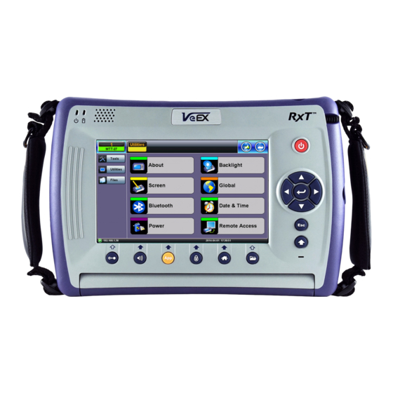
- Page 9 RXT-1200 is a flexible Modular Platform for nodes and field applications. RXT-1200 offers a modern test platform architecture, with a broad range of available test modules covering Access (copper and fiber), Metro, Transport and Core technologies.
-
Page 10: Front Panel
3.1 RXT-1200 Overview 3.2 Front Panel 3.2.1 LEDs Power LED: A single LED indicates the power state of the unit. The LED is off when the unit is powered off. The LED is green when the unit is powered on. -
Page 11: Battery
3.3 Battery The test set platform is equipped with a smart Li-ion rechargeable battery pack, which is located on the rear of the unit. The battery will be partially charged upon delivery, so it is recommended to fully charge the battery before use. Please charge the battery at room temperature to preserve its life and to obtain maximum charge. - Page 12 All-in-One test module reduces CAPEX Optimized for engineers or technicians installing and maintaining OTN, SDH/SONET, and Carrier Ethernet networks transporting legacy and next generation Mobile Backhaul networks Flexible software platform allows for multiple test applications running simultaneously User defined test profiles and thresholds RXT-4100/4100+ Multimode and Singlemode Wavelength options - 850, 1300, 1310, 1490, 1550, 1625 &...
- Page 13 Optional Built-in Visual Fault Locator Optional Optical Power Meter Optional CWDM Light Source via OTDR port Upload OTDR traces and Fiberscope images directly to Fiberizer Cloud via wired or wireless internet connection Universal 2.5 mm optical interfaces with inter-changeable optical adaptors (SC/FC/ST/LC) RXT-4113 CWDM wavelengths per ITU-T G.694.2 (18 Channels) DWDM wavelengths per ITU-T G.694.1 (C-band, 1527.99 to 1563.86 nm, Channel #s 17-62) in 50, 100 0r 200 GHz steps...
- Page 14 Soft LED indicators RXT-6000e CFP2 (LR4 & SR10) and QSFP28 interfaces for 100GE, OTU4 and 50GE applications Supports IEEE 802.3bj Clause 91 RS-FEC as required for SR4 and SR10 CFP4 support via CFP2-to-CFP4 adapter QSFP+ for 40GE, OTU3 SFP28 interface for 25GE, 32/16G FC, 24G CPRI 10 and 25G eCPRI Layer 4 with RS-FEC SFP+ for 100Base-FX, 1000Base-X, 10GEBase-X, OTU2/2e/1e/1, STM-64/16/4/1/0, OC192/48/12/3/1, and Fibre Channel 16/10/8/4/2/1G and CPRI up to 12G RJ45 for 10/100/1000Base-T applications Optional PDH/DSn with standard connectors...
- Page 15 RXT-XXXX Test Modules (Native) New self-contained test modules specifically designed for the RXT-1200 platform (no adapter required). Offer new V300 style GUI It includes Sunrise Telecom’s original RXT-2600 SHDSL.bis test module, which is the only legacy module supported by RXT-1200 Other RxT-1000 modules are not compatible with the new RXT-1200.
-
Page 16: Home Screen
3.5 Home Screen 3.6 Quick Access Menu This multi-tasking section provides convenient and immediate access to system features, connectivity, accessories, results, etc., always at your fingertip. Those features are always available, independently of whether tests are running or not. RXT1200_Platform_Manual_RevB01 Page 16 of 117... - Page 17 Go back to TOC RXT1200_Platform_Manual_RevB01 Page 17 of 117...
-
Page 18: Getting Started
4.0 Getting Started 4.1 Initial Settings 4.1.1 Change language and user interface style Before using the platform, set the language and user interface style as needed. By default, the user interface style is set to USA if the unit is shipped to North America and to International if the unit is shipped to outside North America. International user interface style USA Interface style To change the GUI language and user interface style... -
Page 19: Understanding Test Application Gui
4.2 Launching Test Applications A Quick Guide is always presented in the Home screen after boot up. This procedure can be started at any time, from any screen or menu. 1. Select an empty Test App button. Up to two independent tests can run simultaneously (test set or test module dependent) Some test applications may require two port groups (e.g. - Page 20 Utilities Button: Tap this button access RXT Utility functions Or press the orange App rubber button to toggle. B. Active Test Application GUI - Shows the Test Port Group being used and the Test App ID (Rate / Technology) Tap this button to release the Test App or change its Test Mode. C.
-
Page 21: Utilities
5.0 Utilities 5.1 Platform Settings This section provides settings for the global parameters of the test set or platform (system settings). Settings Menu 5.1.1 About This section provides information about the software version, serial number, and MAC address of the management port of the unit, as well as a list of software licenses (optional test features) currently loaded in the test set. -
Page 22: Screen Calibration
Utility Settings - About - Software Option Utility Settings - About - Software Option 5.1.2 Screen Calibration Go to this section to calibrate the touch screen. Utility Settings - Screen Calibration Follow the instructions and tap on the targets displayed at all four corners. A message displays when calibration is complete. If the RXT1200_Platform_Manual_RevB01 Page 22 of 117... -
Page 23: Bluetooth
5.1.3 Bluetooth VeEX products support a micro USB Bluetooth adaptor offering wireless connectivity up to 10 meters (30 feet). Ultra compact and portable, the adaptor provides an untethered connection between the tester and other Bluetooth compatible devices such as a Notebook PC or cell phone, so the user can transfer test result files quickly and easily without having to hassle with memory sticks or Ethernet connections. - Page 24 Bluetooth - Devices Tab Bluetooth - Devices Tab Bluetooth - Connection - Passcode Setup Press Scan to check for available bluetooth devices. Once scanning is complete, a list of discovered Bluetooth devices will be listed. Please ensure the peripheral device is set to Discoverable during Scanning and Pairing operation. Press Pair BT to begin the pairing process.
-
Page 25: Power
Bluetooth and Mobile phone to a UMTS or 3G network, full data upload service will be required. Bluetooth - Connection Established Bluetooth - Connection Page 2 5.1.4 Power This section provides information about current power source and information about the battery gauge. Tap on the battery icon, on the top bar, to bring battery charge and estimated autonomy information. -
Page 26: Backlight
Utility Settings - Battery Power 5.1.5 Backlight This section provides backlight control of the unit. Power: There are two settings -- one for Battery power and another for AC power. The user has the option to select a timer to turn off the backlight if the unit is not in use. This function helps improve the battery autonomy and preserve LCD life. -
Page 27: Global Settings
Backlight - AC Power Brightness: The user can select the brightness level for Battery and AC operation modes. Backlight - Brightness 5.1.6 Global Settings General Setting Language: An alternative language for the user interface Units: Measurement system (English - feet or Metric - meter) Audible Alarm: When enabled, the test set's buzzer will sound (beep) when alarms and errors are being detected Show Password: Hides/unhides username and password information associated with FTP and related IP functions User Interface: The USA user interface version presents SONET/DSn application-oriented menus, while the International... - Page 28 Utility Settings - General Setting Storage Setting File Name Prefix: Tap on the box to enter the file name prefix using the pop up alphanumeric keypad Profile Deleting: Auto Delete or Prompt User Profile Saving: Auto Overwrite or Prompt User Result Saving: Manual or Prompt User Advanced Saving: On/Off.
-
Page 29: Date And Time
Utility Settings - Lock/Save Screen 5.1.7 Date and Time This screen allows the user to set the date and time according to time zone or user requirement. Daylight savings are automatically enabled in the utility. Date Setup Time Zone Setup Go back to TOC RXT1200_Platform_Manual_RevB01 Page 29 of 117... -
Page 30: Remote Access
Using command line interface (CLI) scripts via SSH connection ReVeal RXTS PC software This VeEX application allows users to connect to the test set, using the platform’s IP address. ReVeal intuitive user interface offers the following functions: Test Profiles Management: Create, Edit, upload and download complex Ethernet and Fibre Channel test profiles (BERT,... - Page 31 Remote Access VNC Viewer - Enter Server Address VNC Viewer - Password Prompt Remote access via web browser: Java-enabled web browsers, such as Internet Explorer™, Chrome™, FireFox™ or Safari™ can be used to manage the test set, access information and remotely control it. This useful feature doesn’t require the installation of any remote clients, other than the standard web browser.
- Page 32 certain tablets. The web browser must support Java (tm) Web Super User Password: Defines the password for users allowed to control the test set via standard web browser clients Web Regular User Password: Defines the password given to users who are only allowed to view the test set current screen via standard web browser clients, but not make any changes to test or test set.
-
Page 33: Ez Remote
5.1.9 EZ Remote The EZ Remote functionality allows users to quickly and securely connect to VeEX test sets all over the world, without the need for VPN, port forwarding or public IP addresses. This VeEX hosted service and user interface take care of all the complex tasks required, and present users with a simple application. - Page 34 The basic EZ Remote service is offered by VeEX free of charge. It provides public registration servers to help users and test sets stablish remote sessions, without having to get IT departments involved. All you need is internet access for the test set and a remote user.
- Page 35 3. On the EZ Remote screen, set EZ Remote to Enabled, confirm the URL is ezremote.veexinc.net (without www.), and tap on Apply to connect and establish a session with the EZ Remote server. 4. Provide the resulting URL and Session ID to the intended remote user. 5.
- Page 36 Establish a Remote Access Connection EZ Remote provides two types of services: Remote Control (screen and mouse/touch mirroring) to operate a test set from a different location. Remote Platform Access to access information stored in the remote test set, such as Test Results, Profiles, User Manual, Screen Captures (screen shots), information about the test set (Home) and its local IP address.
- Page 37 4. Depending on the type of test set used, shortcut buttons may be provided below the mirrored screen, allowing access to functions provided by physical buttons on the instrument, such as Settings, Home, Save Test results. Click or tap on the shortcut to activate it.
- Page 38 Save Test Results To save the results of a test, from the remote computer, press the Save button below the screen image. Then use the pop-up keypad and/or the PC keyboard to enter the file name and add any extra details (if Advanced Save is enabled). RXT1200_Platform_Manual_RevB01 Page 38 of 117...
- Page 39 Access Remote Test Result Files The Remote Platform Access tab provides links to access test results, test profiles, screen shots, the user manual and other information stored in the test set. A tab will open up for each selection made, allowing for quick access to each fuction. Pofiles Test Profiles are configurations saved by the user that can be retrieved and reapplied to the test set.
- Page 40 Remote Control has been replaced by EZ Remote tab. Manual The feature provides access to the user manual that is built into the test set. In this application, the use of a local copy of the PDF file is reccommended as the PDF client in the local computer is most likely faster than accessing the remote one and may offer better tools and fuctions, including search capabilities.
-
Page 41: Vf Noise Calibration (Microphone)
computer. Screen captures can be made using the Lock button (Ï) on the test set or from the remote computer, using the links provided or the respective F-key on the computer’s keyboard. The screen capture function can be enabled in >Utilities >Settings >Global >Save Settings. -
Page 42: Hign Precision Clock Sources
Stay silent while the calibration is in progress. If a headset is used for ISDN or VoIP calls, it must be plugged in during the calibration process. Go back to TOC 5.1.12 High Precision Clock Sources GPS Receiver (HW Option) The optional high-sensitivity GPS module (built-in) provides accurate Phase alignment and Coordinated Universal Time (UTC) synchronization to the test set, in the form of internal pulse-per-second (1PPS) clock synchronized to the standard second and time stamps. - Page 43 GPS-Disciplined Clock When GPS and Atomic Clock options are installed and enabled, the Atomic Clock uses the GPS signal to calibrate its frequency (10 MHz) and timing references (1PPS), to improve their accuracy and stability. The Atomic Clock 1PPS phase is disciplined to the UTC to align it with the standard second.
-
Page 44: Help
GPS Lock The time to get an stable clock output varies depending on the conditions, antenna type and installation, sky visibility and whether or not the test set has changed position. Using the test set for the first time on a new site (different geographical position) would increment the time to its first satellite lock. -
Page 45: Veexpress
5.3 VeExpress VeExpress is a cloud-based asset management system. VeEX VeExpress cloud services is included with every test set. It allows the following services / functions: Delivers Software/Firmware Updates and Upgrades directly to the test set. Makes any new Purchased or Rented licenses (new functions) assigned to the test set immediately available for testing. - Page 46 Up-to-date list of licenses assigned Permanent = Purchased, owned (users can still share permanent licenses by releasing the option from one test set and assign it to another) Leased = Rented, temporary Displays remaining time (Days and Hours) Countdown starts upon first assignment Both permanent &...
- Page 47 2. The install package is in internal memory. 3. Turn the test set OFF. 6. Power the test set ON. 7. The test set software is now up-to-date. Go back to TOC RXT1200_Platform_Manual_RevB01 Page 47 of 117...
- Page 48 5.4 R300 Server (Advanced Management) The R-Server is a centralized server repository for test results. Technicians in the field can register their test set on the R-Server and upload test results directly to the server. To enter the R-Server result upload function, there must be an IP connection established, otherwise a reminder message will pop Register 1.
- Page 49 3. When the test set registration is complete and approved by the R-Server manager you can select Check function key to verify that your test set is authorized. Once your test set is authorized, you can proceed to Upload. Upload To upload result files to the R-Server, tap the Upload tab and select the desired files.
-
Page 50: Software Upgrade
The RXT-1200 Platform includes the bootloader, OS and system-wide (common) features. Its software update package can be identified as RXT-1200-veex.tar.gz. The RXT-1200 Platform uses the traditional V300 upgrade procedure to update the System. The software upgrade packages can be downloaded from www.veexinc.com, or using the test set’s built-in VeExpress client. - Page 51 The built-in VeExpress client downloads the uncompressed RXT-1200-veex.tar.gz upgrade package directly to the root of the memory stick attached to the test set, so the System software upgrade process can be started right away. 5.5.2 Module Software Upgrade Procedure 1. Obtain the required RXT-1200-300sm.tar.gz, RXT-1200-320sm.tar.gz and/or RXT-1200-OTDR.tar.gz, upgrade files.
- Page 52 Press Yes to update the MTT module’s firmware. This process doesn’t require the USB memory stick. MTT modules updated to work with the new RXT-1200 may no longer be fully compatible with older SunSet MTT chassis or RxT- 1000 platforms.
-
Page 53: File Manager
6.0 File Management V300 Style File Manager 6.1 File Manager: Working with Saved Results, Profiles, Images From Utilities go to >Files >Saved. Displays all results stored in the test set Use the check box to select the desired files. Tap on any column header to sort by that specific parameter. Tap again to change the sorting order The U/L button lock and unlock files to prevent accidental deletion. - Page 54 Makes it easier to isolate desired types of results from all other test results stored in the test set Reduces the number of pages displayed Activate Filters Use the stylus to tap on the Y+ icon Check mark the desired attributes Filters parameters can be combined Reset Filters Press the Show All button.
-
Page 55: Usb Memory Browser
6.2 USB Memory Browser USB Tool The USB tool can be found in the Utilities section, under >Files >USB. It provides users with basic memory stick management tools, to browse and interact with its contents without the need of a PC: Reload: Refreshes the USB stick info Delete: Erases the selected files or folders Up: Exits the current folder and moves up to a higher folder in the file tree hierarchy. -
Page 56: Manage Sd Card
>Files >Saved >To USB backup utility or Delete function if the Data partition is nearly full. The Format function is exclusively a maintenance tool. Use ONLY when instructed by a VeEX Customer Care representative. It erases all the information stored in the test set. -
Page 57: Tools
7.0 Tools 7.1 IP Tools The 10/100BaseT management port is located on the right hand side of the unit. This port can be used to connect to the unit for management purposes (results retrieval, software upgrade, remote connectivity, etc.). You can access the management port configuration on the Tools > IP Tools menu. 7.1.1 setup By detault the IP configuration is set to DHCP and the unit will automatically attempt to connect. - Page 58 Static Setup 7.1.2 IP Connection Status Ensure the Status is PASS before continuing with any IP tests. If the connection fails, go back to the setup screen to verify that the parameters are entered correctly. Verify that the Ethernet cable is properly connected on the management port. DHCP: PASS indicates that an IP address has successfully been assigned.
- Page 59 Number of Pings: Press the field and use the alphanumeric keypad to enter the number of ping attempts that will be performed to reach the network device. If Continuous Ping is selected, the user is not required to enter the number of pings. The test set will continuously ping the target host until the user presses Stop.
- Page 60 7.1.4 Trace Route Trace Route is a common method used to find the route to the destination IP address or URL. It is often used to identify routing problems and unreachable destinations. All the remote IP addresses and their response times are displayed indicating possible network congestion points.
-
Page 61: Net Wiz
7.2 Net Wiz Net Wiz verifies the status of each IP address in the user selected range, by using ARP (Address Resolution Protocol) and ICMP test. 7.2.1 Net Wiz Setup Profile: Drop-down selections are Default, Delete, Save, Save As... Begin IP: Set the start address for the desired IP range using the numeric keypad End IP: Set the end address for the desired IP range using the numeric keypad Select the test by placing a check mark in the corresponding box of any of the following: ARP, Ping Net Wiz Setup... - Page 62 Global reports: Total number of devices found Number of devices (Routers, Servers, Hosts) Net Wiz Results - Devices - Global Detail displays the Attribute, MAC and IP Addresses, and Ping test results of each device discovered. Net Wiz Results - Devices - Detail Go back to TOC RXT1200_Platform_Manual_RevB01 Page 62 of 117...
-
Page 63: Wifi Wiz
Plug the WiFi adaptor into the USB port. Allow at least 30-45 seconds for the unit to detect the wireless adaptor and for the software driver to load. Products support USB wireless adaptors supplied by VeEX only and have the necessary software driver built into the test set. - Page 64 AP List The following information is displayed for each AP: SSID name of the AP BSSID (MAC address) of the AP 802.11 protocol version supported by the AP Max data rate supported by the AP AP's radio channel number Lock symbol indicates if security is set on the AP (WEP, WPA or WPA2). When the AP is unsecured, no lock symbol is displayed Signal strength of the AP Select one of the Access Points (AP) to start a connection.
- Page 65 WiFi Wiz Connection Setup Status The Status Tab displays the following information on the connection: Connection Status ESSiD: Name connected to BSSiD: MAC address of wireless router/device connected to Channel: WiFi Channel # connected to Encryption: Encryption type Mode Signal: Radio signal level (dBm) Link quality score Max data rate...
-
Page 66: Arp Wiz
WiFi Wiz Connect IP 7.4 ARP Wiz ARP Wiz uses the Address Resolution Protocol (ARP) to verify the status of each IP address in a user-selectable IP range. ARP is the standard method for finding a host's hardware address when only its network layer address is known. In other words, ARP is used primarily to translate IP addresses to Ethernet MAC addresses. - Page 67 Result The MAC addresses associated with active IP addresses in the range are displayed. If no MAC address is associated with the IP address, a FAILED status is displayed. ARP Wiz uses the ARP protocol and can only work within the same subnet as the IP address provided to the test set in IP Status ARP Wiz Result Go back to TOC...
-
Page 68: Advanced Tools
7.5.1.1 Fiber Scope The VeEX digital inspection fiberscopes are fundamental tools for evaluating fiber optic connectors for dirt and end face quality. The handheld probe design enables easy inspection of patch cords and difficult to reach bulkhead or patch panel connectors. Clear images are displayed on the test sets for immediate analysis and can be saved for record keeping. -
Page 69: The Importance Of Fiber Connector Inspection
DI-1000 digital inspection scope DI-1000MPO multi-fiber and single fiber inspection scope DI-3000 Wi-Fi Autofocus digital inspection scope Go back to TOC 7.5.1.2 The Importance of Fiber Connector Inspection Dirty or scratched connectors introduce loss, increase ORL and/or damage other connectors (Losses becomes more critical at higher data rates). - Page 70 For DI-1000/DI1000MPO, plug in the USB Type A (male) end into the USB Type A (female) port of the TX300S platform. This applies for MTTplus and RXT-1200 platform On the DI-3000, connect one end of the micro-B USB OTG cable to the micro-B USB port on the scope and the other end (USB Type A (male)) to the fiberscope USB Type A (female) port.
- Page 71 Fiber Scope, located in Tools> Advanced menu Fiber Scope selection menu (USB for direct connection, Wi-Fi for DI-3000 AP) FiberScope Setup menu - Page 1 Scope mode: a dropdown menu option that the Fiber Scope application uses to determine the fiberscope connection method to be used. Local: direct USB connection through micro-B USB port and micro-B USB to USB Type A OTG cable for DI-1000, DI-1000MPO, and RXT1200_Platform_Manual_RevB01 Page 71 of 117...
-
Page 72: Setup Page 2 And Capture Tab
DI-3000. Remote: [Obsolete], to be removed in next release (assigned task). Remote DI-3000: dedicated auto-connect option for DI-3000 Wi-Fi usage only. Auto Save: a dropdown menu option that defines the Fiber Scope application to provide ease of use saving capabilities. If Autosave option is enabled, the unit automatically saves and creates the filename using Trace ID field content after the specified test function. - Page 73 Auto center/Crop: this function takes current video frame and centers it by the detected fiber image inside program window, i.e. in case of long (extension) tips or handshaking. Initially, the user will see a blank screen. Descriptions of sidebar options are provided below. Resume: Turns on or stops the video capture feed of the fiberscope.
- Page 74 a. Optionally, the autosave function can be disabled in favor of manual saving. Manual saving is done in the Results tab and pressing the Save button after the user has finished inspecting a fiber endface. Filename labeling and auto-saving mode setup parameters Next, the user will navigate to page 2/2 of the setup tab to fill in the remaining fields: Analysis parameters, tip type, and optional auto-center/Crop.
- Page 75 Autosave to Tap Enabled Autosave after Freeze Enabled Pass/Fail IEC analysis table RXT1200_Platform_Manual_RevB01 Page 75 of 117...
- Page 76 Result tab – Tree structure file storage RXT1200_Platform_Manual_RevB01 Page 76 of 117...
- Page 77 Internal SD Card Format USB Export Results – VEEX_OTDR_Results for single-fiber endface and HTML test report MPO Fiber Analysis Workflow: 2. Since Autosave functionality is NOT supported for MPO in the Fiber Scope testset app, the user will have to define the following fields: Job ID, Cable ID, Fiber ID, Test ID in the Results tab (manual save) at the end after scoping a full group of MPO fibers.
- Page 78 Analysis: ON Auto-Freeze: OFF (user can optionally have it on, but it makes the scoping process slower). Rects/Dots: User’s personal choice unless directed. Dots setting is default. Shake: OFF 5. MPO mode changes the fields in Page2 setup mode to the MPO equivalent Analysis parameters: Either PC, SM RL ≥...
- Page 79 Comment: When the scope capture feed is on, it is likely that the MPO fiber is not in focus or present on the screen. The key-up and key-down adapter that comes with the DI-1000MPO standard package is a straight-through connection so the MPO fiber # at the start matches the MPO fiber # at the end (not flipped).
- Page 80 Action 2: The screenshot is added to the montage list (left), and the user moves to the next fiber (right). RXT1200_Platform_Manual_RevB01 Page 80 of 117...
- Page 81 Action 3: Same as Action 1… Press Save or Fiberscope button to confirm or capture screenshot for MPO fiber for the nth fiber. MPO-12 cable completed. All PASS 7. With the MPO cable inspection completed as seen above (e.g. MPO-12 as example), the user will navigate to the Results tab and press Save.
- Page 82 Results tab menu and Manual Save procedure There is no autosave naming/function for MPO/MTP inspection. This is only a function of single-fiber inspection.. 8. Enter the results saving parameters: Job ID, Cable ID, Fiber ID, Trace ID, and Comments (typically optional) and press OK. Several seconds later, the file structure will show up as saved in internal storage.
- Page 83 Clicking on the trace symbol row displays the thumbnail image on bottom right corner To view results for an MPO-12 cable on the unit, navigate to the mpo heading on on the saved trace and press Load. This will display a screen similar to the ALL PASS screenshot, and the user can tap each individual screenshot to view the individual MPO fibers.
- Page 84 Fiberizer Cloud account credentials User: the field that specifies the email address the user registered the Fiberizer Cloud account with. Password: the field that specifies a memorized secret code that the user registered the Fiberizer Cloud account with. URL: the default location of Fiberizer Cloud [unchanged] Project: the field that allows users to view and select created project folders as a save location on Fiberizer Cloud account.
- Page 85 Uploading progress bar for Fiberizer Cloud results transfer (must be connected to Wi-Fi hot spot) Push → In Sync (results are already updated) The user can check under the Jobs folder where the saved MPO cable folder was uploaded to and use Fiberizer Cloud to create professional reports or serve as an online storage backup.
- Page 86 In the red highlighted box, this line shows the file structure that was defined from the testset transferred to Fiberizer Cloud. Users can create MPO fiber report templates in PDF here and Fiberizer Desktop Plus (Windows PC equivalent). USB Export Results – VEEX_OTDR_Results for MPO endfaces MPO endface test results html page RXT1200_Platform_Manual_RevB01 Page 86 of 117...
-
Page 87: Optical Power Meter (Opm)
The optical power meter application (Fiber Tools or built-in OPM w/OTDR module) provides an interactive, optimized user experience alternative in performing measurements with the FX4x/Fx8x series OPM/OLTS for customers who possess certain VeEX test sets. Optical power meters are used to measure the average power and relative loss (attenuation) of the fiberoptic system. The external optical power meter test application allows users to add-on fiberoptics test functionality (tethering application) to a non-fiberoptics based VeEX testset (CATV, Ethernet…). - Page 88 USB-Type A port of the testset to the micro-B USB port of the power meter. V150 Platform (FX150/FX150+, FX180/FX180X, MTX150x, CX310…): The user will need a micro-B USB to micro-B USB (OTG) cable purchased from VeEX (manufacturer guarantee) or aftermarket 3rd party brand to connect the FX4x/FX8x power meter ‘s micro-B USB port to the micro-B USB port of the testset.
- Page 89 dust caps closed. External power meter interface notification The following image is the front panel of the testset GUI that users will majority work with, having almost all the functions (except permanent saving) readily accessible within the same screen and simple, button presses. OPM Home Screen when first connected Wavelength: this pull-down menu specifies a list of calibrated wavelengths for the user to match the transmitted signal being measured.
- Page 90 Zero dark currents with fully closed dust caps covering the ports OPM server on: this function broadcasts the current IP address on the current network for users to connect to the testset’s module built-in optical power meter through Ethernet/TCP/IP using Fiberizer LTSync Windows Desktop software for remote control and access. OPM Server Function Enabled of OPM testset app.
- Page 91 It is also possible for the user to use a VeEX approved Wi-Fi USB dongle for RXT-1200, MTTplus, and TX300S chassis/built-in Wi-Fi in VS- 150 platform for the IP address and deselect the Ethernet connection button to type in IP address and port and press the Live Mode button.
- Page 92 absolute power measurement displayed 0 dB loss reference established, saved initial reference is 2nd row, 2nd entry dB loss measurement 5. The dB loss measurement can be read off the 1st row, 2nd column entry. Press Hold (to pause the reading) and Acquire to log the current measurement reading.
- Page 93 Optical light sources are used to transmit the laser source under test to measure the loss (attenuation) of the optical network. The light source tab can be used to control the VeEX testset built-in or tethered OLTS light source. RXT1200_Platform_Manual_RevB01...
- Page 94 Supported wavelengths on FX45 OLTS (1310/1550) configuration Lasers: Select a calibrated wavelength from the dropdown list to transmit light energy. Available lasers wavelengths dependent on FX4x/FX8x optical loss test set (OLS + OPM) configuration. CW: Continuous Wave mode. The light source is 100% duty cycle (100% transmitting) 270 Hz, 1000 Hz, 2000 Hz: different modulation frequencies generated for varied fiber cable identification with a live fiber identifier.
- Page 95 Trace ID: general OTDR-derived measurement parameter that consists of timestamp and VeEX optical ID serial number. Comments: a field that can be used to fill in other relevant information to the user and/or not available with the standard VeEX OTDR style fields.
- Page 96 Cleared table when the prompt is OK(ed) or user presses the Remove button to delete results Cleared table when the prompt is OK(ed) or user presses the Remove button to delete results. Optical Power Meter application Results tab. Note the tree file structure The Results tab provides management functions for Fiberizer Cloud upload and download activities and typical file operations (Save, Rename, Delete, USB Export (External device save), …).
- Page 97 Modify – Expanded options Fiberizer Cloud account credentials. Press Save to record changes. Fiberizer Cloud account credentials. Press Save to record changes. Pull: this function downloads the files from a project folder on Fiberizer Cloud to the testset. RXT1200_Platform_Manual_RevB01 Page 97 of 117...
- Page 98 Pop-Up window to download OPM results to the testset USB export: When a USB drive is inserted into the testset, the user can highlight the folder/files to press this function to transfer them over to view on a computer. It also serves as a physical backup option if the user is uncomfortable leaving the results on the testset or uploading to Fiberizer Cloud.
- Page 99 Start acq to enable the application to log the current measurement periodically (the time set). Press Stop acq when done. Auto-logging OPM measurements with Start Acq function Table tab to show counter of logged measurements. Stop Acq to stop logging Displayed logged measurements –...
-
Page 100: Wifi Spectrum Analyzer
Go back to TOC 7.5.3 WiFi Spectrum Analyzer WiFi SA is a portable spectrum analyzer on a USB dongle that displays all RF activity in the WiFi bands (e.g.,s wireless networks, cordless phones, microwave ovens, Bluetooth devices, etc.). It offers the following capabilities: Helps determine the best available WLAN channels quickly for optimal performance Helps to visualize and locate RF signals in the 2.4GHz and 5GHz spectrums Discover and remedy competing access points... - Page 101 WiFi SA - Planar View Planar View Traditional Spectrum Analyzer view with Max, Average, and Current results Displays RF activity in real time and tracks average and max values over a given period WiFi SA - Topographic View Topographic View Similar to a density map - plots frequency versus amplitude Uses a special color scheme to assign colors to frequency amplitude points and to identify how often a particular coordinate is recorded...
- Page 102 WiFi SA - Spectral View Spectral View Waterfall type view across the whole band - graphs amplitude levels over time Uses color to pick out the relative signal strength at each point in time Great tool for troubleshooting intermittent problems, since it highlights devices that are perhaps emitting only short bursts of noise For example - discover microwave oven in the kitchen interfering with WLAN WiFi SA - Signatures Signatures...
- Page 103 WiFi SA - Inspector Inspector The Inspector button setup allows the user to measure the frequency of the RF activity or interference of interest When selected, a prompt and result box appears WiFi SA - Inspector - Result Inspector Button - Result Identifies frequency and amplitude Current, Average, and Maximum amplitude values provide an indication of level fluctuation over measurement period RXT1200_Platform_Manual_RevB01...
-
Page 104: Data Card
To establish an IP connection using a data card, please make sure that the data card is connected on the USB port. Note that only datacards provided by VeEX are supported and have the driver necessary for connection. The Data Card icon, as shown below, will appear at the bottom of the screen. -
Page 105: Wifi Inssider
Once a connection has been established: The D for Data in the icon turns green The connection details are displayed in the IP Tools Status tab (shown below) It will automatically reconnect if the test set is powered off/on and you are in a good reception area It will automatically reconnect if you enter a bad cell area and return to a good one 7.5.5 Wifi inSSIDer WiFi inSSIDer Home... - Page 106 When the AP is unsecured, no lock symbol is displayed Signal strength of the AP Access Points in the 5.0GHZ spectrum can only be displayed if the VeEX USB Wifi adapter supports 802.11a/n or 802.11 a/n/ac. Refer to the USB Wifi adapter specifications.
- Page 107 Graph Use the Right/Left/Up/Down function keys or the arrow keys on the unit's keypad to navigate the graph and get additional information for the access points. Detailed information for each Access Point includes: SSID: name of the AP AP's radio Channel number Signal strength (dBm) Number of co-channel: Number of APs using the same radio channel Number of Overlapping APs: Number of APs using channels whose frequency band overlaps with the AP.
- Page 108 GNSS Receiver On 4. Turn the GNSS Receiver = ON. 5. Set the Satellite System = GPS 6. Set In-survey time (s) = 600, which is the time window used by the GNSS Receiver to assess stable location, using the specified accuracy (below).
- Page 109 Discipline Source 3. Verify that 1PPS Signal Health = Valid, to confirm that the one-pulse-per-second signal is being detected. 4. Set Discipline Profile = Custom. 5. Set Time Constant (s) = 60 (this small window is only used to expedite the initial phase alignment process). 6.
- Page 110 Discipline Source Phase Measurement 2. Close the Phase Graph and verify that the Disciplining Status gets into Locked mode. At this point the test set’s internal “Atomic 10MHz” frequency and “Atomic 1PPS” timing reference signals can be considered accurate and stable.
- Page 111 Virtual Observer Building such maps usually takes >24 hours, to allow each satellite to complete one cycle over the antenna (not to be confused with their ~12-hour orbital cycles). Examples of 2D Linear and Cosine projection (polar) grids, as well as actual satellite trails recorded This type of tool can also be used to evaluate and benchmark different antennas in real life and under the same conditions.
- Page 112 GNSS Receiver Off 3. Go to >Tools>Advanced>More>GNSS. 4. Select the Time Zone from the Time Zone Offset: drop-down list box. 5. Enter a Test Name from the File Name: drop-down list box. 6. Select the Duration of the test from the Duration: drop-down list box. GNSS Setup 7.
- Page 113 GNSS Start Menu GNSS Start GNSS Results RXT1200_Platform_Manual_RevB01 Page 113 of 117...
- Page 114 8. To save Results to USB tap on the Arrow and then tap on Save Results To USB. GNSS Save Results Go back to TOC RXT1200_Platform_Manual_RevB01 Page 114 of 117...
- Page 115 The built-in web browser uses the management port IP connection. An active IP connection can be established either through Ethernet, WiFi or datacard ports. The web browser defaults to VeEX's website. Use the web browser's navigation bar to enter the name of the website you wish to reach.
- Page 116 All applicable products imported into the EU market after July 1, 2006 must pass RoHS compliance. For more information about RoHS as it relates to VeEX Inc, go to the VeEX web site at www.veexinc.com/RoHS.
- Page 117 With a blend of advanced technologies and vast technical expertise, VeEX’s products diligently address all stages of network deployment, maintenance, field service turn-up, and integrate service verification features across DSL, Fiber Optics, CATV/DOCSIS, Mobile backhaul and fronthaul (CPRI/OBSAI), next generation Transport Network, Fibre Channel, Carrier &...
Need help?
Do you have a question about the RXT-1200 and is the answer not in the manual?
Questions and answers