
Subscribe to Our Youtube Channel
Related Manuals for VeEX FX120


Summary of Contents for VeEX FX120
- Page 1 FX120/FX120 Lite User Manual XG(S)-PON Analyzer & XG(S)-PON Analyzer Multi-Gig Service Test Set P/N D07-00-153P Rev. B01...
- Page 2 Please direct all questions to your local VeEX® Sales Office, Representative, or Distributor. Or, contact VeEX tech- nical support at www.veexinc.com. No part of this user manual may be reproduced, translated into a foreign language, or be transmitted electronically without prior agreement and written consent of VeEX Incorporated as governed by International copyright laws.
-
Page 3: Table Of Contents
Ethernet Single Port LED Status Lights Mode/Port Selection GPON Preparing for PON Testing OPM Setup GPON/XGS-PON Test Procedure GPON and XGS-PON Threshold Standards Synchronizing the FX120/FX120 Lite with the ONU Activation Process Table of © VeEX Inc. All Rights Reserved. Contents... - Page 4 Auditing/Rebuilding a Fiber Distribution Hub (SuperPM option) Splitter Analysis (optional) Distribution Analysis (optional) Fault Locator Screen Help EPON/10G-EPON Testing EPON/10G-EPON Test Procedure Synchronizing the FX120/FX120 Lite with the ONU Activation Process EPON Thresholds Ethernet Setup Ports IP Connection Setup Status...
- Page 5 V-TEST Run a Speed Test Server Selection Modes Speed Test Modes V-PERF Server/Client - Unidirectional Configuration and Results Bi-Directional Configuration and Results (VeEX Enhanced Testing Methodology Implementation) V-FTP Run a FTP Speed Test Platform Functions Results & Files File Manager...
- Page 6 Certifications and Declarations About VeEX Customer Care FX120 Quick Guide Step 1: Power on Test Set Step 2: Configure Test Profile Step 3: Insert Patch Cord into FX120 OLT test port. Table of © VeEX Inc. All Rights Reserved. Contents...
- Page 7 Step 4: Connect Splitter to FX120 ONU/ONT test port. Signal and Synchronization Status Step 5: Save Results Step 6: View Results & Generate Report Other Test Features Table of © VeEX Inc. All Rights Reserved. Contents...
-
Page 8: General Information
VeEX Inc., and to use it solely as intended and described in this manual. The purchaser is prohibited from copying, reverse engineering, decompiling, or disassembling the software. ... -
Page 9: Warranty
For warranty information on VeEX Inc. products, go to www.veexinc.com. To activate the warranty, please register your production at www.veexinc.com/Support/ProductRegistration. Patent Information VeEX Inc. product hardware and software may be protected by one or more patents on file with the United States Patent Office. Documentation Conventions... -
Page 10: Safety Information
Do not operate the instrument in the presence of flammable gases or fumes or any other combustible environment. VeEX Inc. assumes no liability for the customer's failure to comply with safety precautions and requirements. Lithium-ion Battery Precautions Lithium-ion (Li-ion) battery packs are compact and offer high capacity and autonomy, which make them ideal for demanding applications, like providing long lasting power to portable test equipment. -
Page 11: Optical Connectors
3. Never use a fiber microscope to check the optical connectors when the laser source is active. Electrical Connectors Telephone lines may carry dangerous voltage. Always connect the electrical test ports to known test interfaces which carry low level signals. © VeEX Inc. All Rights Reserved. Safety Information... -
Page 12: Introduction
Introduction The VeEX® FX120PON Analyzer and Multi-Gig Service Test Set/ FX120 Lite PON Analyzer is designed to assist with PON service activation and aid in troubleshooting as well as support Layer 4+ testing. When con- nected at the customer site between the splitter and Optical Network Unit/Optical Network Terminal... -
Page 13: Optical Specifications
Downstream 1577 - 1578 nm OLT Signal -35 to +2 dBm Spectral passband 1572 to 1582 nm -28 to +12 dBm Upstream ONU/ONT 1310 nm Signal (power meas- urement), burst mode Spectral passband 1300 to 1320 nm © VeEX Inc. All Rights Reserved. Introduction... - Page 14 Requires activation of PON-ID functionality in PON system per ITU- T G.984.3 Amd 3 Active ONU/ONT List Standard offering PLOAM Decoder Standard offering Fault Locator option Wavelength (nm) 1625 ± 10 nm Passband (nm) 1610 to 1680 Introduction © VeEX Inc. All Rights Reserved.
-
Page 15: Product Specifications
For non-reflectance, distance measurement accuracy can be up to ±2.5%. Laser Safety Class 1 per 60825-1:2014 edition Product Specifications The most recent product specifications can be downloaded from the product page of the VeEX Inc.website (www.veexinc.com). © VeEX Inc. All Rights Reserved. Introduction... -
Page 16: Basic Operation
To power on the test set, press for approximately two seconds, until the test set beeps once. See Hard But- tons and Interface for more information on the test set's buttons and interface. Basic Operation © VeEX Inc. All Rights Reserved. -
Page 17: Connector Panel
Connector Panel The FX120 connector panel features an ONU port (to ONU), an OLT port (to OLT), a native RJ45 and SFP+ cage, and an optional fault locator port. A. Fault Locator: Drop Fiber Testing B. ONU: port to Optical Network Unit C. - Page 18 Although most common optical transceivers are considered safe, please follow standard eye safety procedures and common sense (e.g., avoid using optical scopes or looking directly at active connectors). Basic Operation © VeEX Inc. All Rights Reserved.
- Page 19 C. Home: Returns the screen to the home menu. Pressing the Home key for 3 seconds puts the unit in sleep mode. Once in Sleep Mode, press the Home key for 3 seconds to return to normal operation. More about sleep mode This is not full power shutdown. © VeEX Inc. All Rights Reserved. Basic Operation...
- Page 20 Right side + Save: Saves the screen (bmp) Right side + Home: Hibernates device More about side buttons Side buttons on the left and right of the unit can reveal menus or other functions depending on the unit Basic Operation © VeEX Inc. All Rights Reserved.
- Page 21 E. Micro-B USB: Use an USB-A OTG cable (optional with purchase) to connect a USB to the micro-B USB port. The port supports memory drives and USB add-on devices such as fiberscopes. An optional Micro-B OTG to Ethernet adapter is also available for network connection. (Only VeEX approved OTG to Ethernet Cables can be used.) G.
-
Page 22: Special Functions
While in Standby mode, quickly press to see the current standby time and remaining battery charge. Press the button again for three seconds to bring the test set back to full operation. Basic Operation © VeEX Inc. All Rights Reserved. - Page 23 Software Install. Backing up all data to a USB memory stick is recommended. To back up to USB, go to >Files >Saved and tap . Refer to "Working with Saved Results, Pro- files, Images" on page 111 for more details. © VeEX Inc. All Rights Reserved. Basic Operation...
-
Page 24: Touch-Screen Display
Clean the surface of the touch screen using a soft cloth and mild detergent only. Do not use alcohol. "Touch Screen Calibration" on page 195 for instructions on how to recalibrate the touch-screen. Basic Operation © VeEX Inc. All Rights Reserved. -
Page 25: Platform Screen Icons
Fiberscope: Indicates that a fiberscope is connected to the unit. Tap the icon to go to the Fiber- scope application. OTDR Viewer: Analyzes standard OTDR .SOR files created by supported VeEX test sets and controls the OPX-BOXe OTDR. © VeEX Inc. All Rights Reserved. - Page 26 FX40/45/48 Viewer: Controls FX40/45/48 optical test loss test sets and analyzes standard OPM files. PON: Access Advanced PON tools Flow: Access the Flow feature to perform and compile multiple tests into a single job report. Basic Operation © VeEX Inc. All Rights Reserved.
-
Page 27: Leds
Tap TOOLS to view PLOAM, and Active ONU. The History button resets the LEDs of past statuses. © VeEX Inc. All Rights Reserved. Basic Operation... -
Page 28: Ethernet Single Port Led Status Lights
If any LED remains red, clean the patch cord connectors that will connect the FX120/FX120 Lite to the ONU/ONT, the FX120/FX120 Lite test ports (To ONU, To OLT), and the ONU/ONT ports. Refer to Inspection for information on inspecting and cleaning fiber connectors. -
Page 29: Mode/Port Selection
IP address automatically (if DHCP is set up). But, the test mode can always be manually switched. Test modes are accessed by selecting the Test Application button . Tap on a technology group then select a test interface. © VeEX Inc. All Rights Reserved. Basic Operation... -
Page 30: Gpon
Fiberscope with Universal 2.5mm UPC and APC male tip, SC/APC bulkhead and SC/UPC bulkhead tips to inspect optical connectors. Patch cord – one to two patch cords depending on what is required to insert the FX120/FX120 Lite between the splitter and ONT. -
Page 31: Opm Setup
In the OPM Setup screen, configure the test profile settings and thresholds according to the xPON class based on the ITU-T and IEEE Test standards or customize a unique profile. Tap Setup on the OPM screen to access the setup screen. GPON OPM Setup menu © VeEX Inc. All Rights Reserved. GPON... - Page 32 XG(S)-PON OPM Setup menu EPON OPM Setup menu GPON © VeEX Inc. All Rights Reserved.
- Page 33 To simplify the view and see the OPM readings only on the main screen, select On for OPM Only. General Setup © VeEX Inc. All Rights Reserved. GPON...
- Page 34 OPM Only View GPON © VeEX Inc. All Rights Reserved.
-
Page 35: Gpon/Xgs-Pon Test Procedure
GPON/XGS-PON Test Procedure The FX120/FX120 Lite is designed for use at the customer premises to aid with ONT/ONU activation and troubleshooting. The FX120 is connected at the customer premises. 1. Power on the FX120/FX120 Lite test set. Testing should start automatically. Restarting meas- urements from the OPM menu (see OLT Information Table) resets items in the OPM Summary screen - the power level graphs and the Active ONU list in Advanced Mode. - Page 36 GPON OPM Setup menu XGS-PON OPM Setup menu 3. Inspect and clean the FX120/FX120 Lite test ports. Inspect and clean the fiber patch cord from the OLT and insert it into the FX120/FX120 Lite OLT test port. Warning: Never look directly into the beam of an active optical source as this may res- ult in harmful eye damage from radiation exposure.
-
Page 37: Gpon And Xgs-Pon Threshold Standards
"GPON/EPON LED Status Indicators" on page 41). 6. Inspect and clean the patch cord connectors that will connect FX120/FX120 Lite to ONU/ONT and the ONU/ONT test port. 7. Connect the FX120/FX120 Lite to the ONU/ONT test port. If 1310/1270nm light is detected, the Status will display OK. -
Page 38: Synchronizing The Fx120/Fx120 Lite With The Onu Activation Process
In order to synchronize with the ONU, the FX120/FX120 Lite needs to see the ONU registration process. There- fore, only connect the ONU AFTER the FX120/FX120 Lite application is already running. Otherwise, unplug and replug the ONU the ONU after the FX120/FX120 Lite application is running if the ONU is already con- nected to the FX120/FX120 Lite. -
Page 39: Opm Test Mode
OPM Test Mode GPON/XGS/EPON PON Diagram Network diagram of the GPON network. Connect the FX120/FX120 Lite between the splitter and ONT/ONU. Do NOT connect the FX120/FX120 Lite between the OLT and splitter. The FX120/FX120 Lite should be connected between the splitter and ONT. - Page 40 XGS-PON Summary Screen EPON Summary Screen GPON © VeEX Inc. All Rights Reserved.
-
Page 41: Gpon/Epon Led Status Indicators
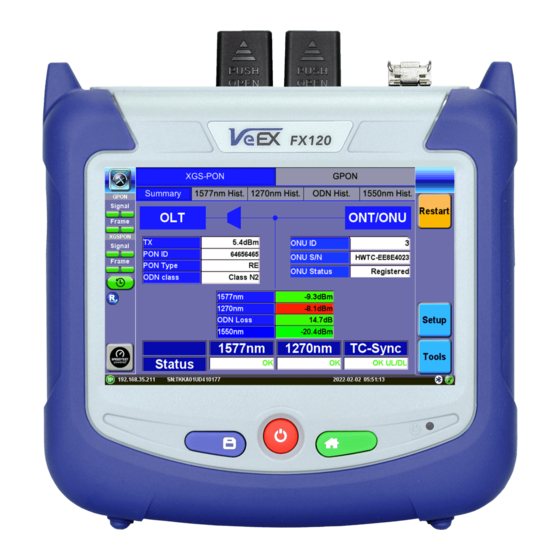
10G EPON Summary Screen GPON/EPON LED Status Indicators On screen LED colors indicate the status of upstream (Up) and downstream (Dn) signals and frame/error detection. GPON/XG(S)-PON Upstream/Downstream LED Status EPON/10G EPON Upstream/Downstream LED Status © VeEX Inc. All Rights Reserved. GPON... -
Page 42: Olt And Ont/Onu Messages And Measurements
The History button resets the LEDs of past statuses. If any LED remains red, clean the patch cord connectors that will connect the FX120/FX120 Lite to the ONU/ONT, the FX120/FX120 Lite test ports (To ONU, To OLT), and the ONU/ONT ports. Refer to Inspection for information on inspecting and cleaning fiber connectors. - Page 43 If the information is not displayed, it may have been missed. Power cycle the ONU to initiate the ranging process again. ONU Status "ONU/ONT Statuses" on page 46 for more information. GPON Signal Measurement Table XGS-PON Signal Measurement Table © VeEX Inc. All Rights Reserved. GPON...
-
Page 44: Signal And Synchronization Status
EPON Signal Measurement Table At any customer location after the OLT and splitter, the FX120/FX120 Lite will display 1490nm and 1310nm sig- nal level values for GPON, 1577nm and 1270nm for XGS-PON, and 1550nm for RF/CATV. ODN Loss is the dif- ference between the transmitting signal from the OLT (TX) and the DS signal level measured at the FX120/FX120 Lite location. - Page 45 1577nm/1270nm/1310nm: If OK is displayed, light in the downstream 1577nm or upstream 1270nm direction or upstream 1310nm is detected. Transmission Connectivity Sync (TC-Sync): OK UL/DL indicates that the FX120 is properly syn- chronized with the OLT and ONU/ONT traffic. No UL/DL indicates the OLT and ONU/ONT are not synchronized properly.
-
Page 46: Onu/Ont Statuses
ONU/ONT Statuses The FX120/FX120 Lite can report three ONT statuses: 1. Registered 2. Unregistered 3. Rogue Registered (Activated) Registered means that the ONT/ONU serial number was acknowledged by the OLT port (aka PON-ID) to be a valid SN so the activation process can continue through the remaining steps. This means that communication between the ONT and OLT was established and continues on. -
Page 47: How To Detect Rogue Onts
ONT. When testing for rogue ONTs, the FX120 should be placed after the last splitter and right before the ONT to capture downstream information. The OLT will send messages to request ONTs to shut down if they are trans- mitting outside their timeslot. -
Page 48: Histogram And Odn Loss History
Downstream and Upstream signals. Tap on the upper left and right arrows to scroll through the meas- urement period. The + and – keys zoom in/out of the time axis. 1310nm Histogram showing Upstream signals 1490nm Histogram showing Downstream signals GPON © VeEX Inc. All Rights Reserved. - Page 49 ODN Loss Histogram shows the budget between OLT TX level and ONT downstream (1490nm) received level. Exceeding the range will cause the ONT to fail to go online. The ODN link budget and optical power loss calculation need to be planned in advance. © VeEX Inc. All Rights Reserved. GPON...
-
Page 50: Advanced Opm Mode
Splitter analysis and Distribution analysis assist in performing an ONT port audit on the splitter and distribution panel. "Splitter Analysis (optional)" on page 56 "Distribution Analysis (optional)" on page 60. Advanced home menu To access the Advanced menu, press the Tools button on the OPM screen. GPON © VeEX Inc. All Rights Reserved. -
Page 51: Active Onu
To see all active ONUs, tap TOOLS to access the Advanced Tools menu. Then, tap Active ONU. To clear the list, tap Clear. White: Registered ONU Red: Unregistered ONU Green: Most recently registered ONU Grey: Rogue ONU GPON/XG(S)-PON ONT/ONU Active Devices EPON/10G EPON ONT/ONU Active Devices © VeEX Inc. All Rights Reserved. GPON... -
Page 52: Ploam Messaging Decoder
Use Setup to filter out unwanted messages to streamline your work. Use the scroll buttons on the side to help navigate and scroll through the messages. To navigate up, scroll up. To navigate down, scroll down. GPON © VeEX Inc. All Rights Reserved. -
Page 53: Ploam Decoder Filtering
PLOAM Decoder Filtering GPON/XG(S)-PON Advanced Tools includes test management and PLOAM Decoder Filter options. Use the PLOAM Decoder Setup to allow or block certain messages to streamline troubleshooting. GPON PLOAM Setup XG(S)-PON PLOAM Setup © VeEX Inc. All Rights Reserved. GPON... -
Page 54: Oc Decode
ITU-T standards. Color-coded for visibility, it is broken down by PON-ID Type, PON ID, Reserved, TX Optical Level Reference, and Transmit Optical Level. To see the OC Decode screen, tap TOOLS to access the Advanced Tools menu. Then, tap OC Decode. OC Decode screen GPON © VeEX Inc. All Rights Reserved. -
Page 55: Auditing/Rebuilding A Fiber Distribution Hub (Superpm Option)
Auditing/Rebuilding a Fiber Distribution Hub (SuperPM option) Use the optional Splitter Analysis and Distribution Analysis features on the FX120 to do a full survey of a street cabinet by identifying all the ONTs by serial number and locating each ONT to each PON ID - both on the split- ter side and on the distribution panel. -
Page 56: Splitter Analysis (Optional)
Process A connection from the FX120 OLT port to a free port (any) on the Splitter Panel allows the FX120 to monitor a copy of all signals happening on all ports. The test set listens to see if there is a signal (capturing the SSN/PID), no signal, or empty port. - Page 57 If the port is empty, mark it "Empty" until the next occupied port is reached. If the port has a patchcord but no letter, mark the port as "No SN". The FX120 will listen to and collect information associated with that port.
- Page 58 In the event of low battery or reboot, the unit will automatically create a restore point in which point the analysis may be resumed, as long as the location and panel type match. GPON © VeEX Inc. All Rights Reserved.
- Page 59 OLT/ONT to that position. restart the connection and the FX120 to detect the information exchanged between them. The SSN Serial Number and/or PON- No action needed. The unit will move to the next ID has been captured.
-
Page 60: Distribution Analysis (Optional)
To use the advanced Distribution Analysis feature: 1. Keep the connection from the FX120 To OLT port to the Splitter (any free port) and connect another patchcord from the FX120 To ONT port to the customer port on the ODF by swapping out the cus- tomer patchcord. - Page 61 ”Empty” until the next occupied port is reached. If the port has a patchcord but no letter, mark the port as "No SN" or "Skip".The FX120 will listen to and collect information associated with that port. It may take up to ten seconds for the OLT/ONT to restart the connection and the FX120 to detect the information exchanged between them.
- Page 62 (in split- ter analysis) Press Skip. The unit will move to the next port automatically. To jump to the next port (in distribution analysis) If no SSN is Press No S/N. detected GPON © VeEX Inc. All Rights Reserved.
- Page 63 OLT/ONT to that position. restart the connection and the FX120 to detect the information exchanged between them. The SSN Serial Number and/or PON- No action needed. The unit will move to the next ID has been captured.
-
Page 64: Fault Locator
2. If using a launch fiber, select the length from the Launch Reel drop-down. 3. Tap Start. Fault Locator If measurement is in green, the test is complete. If measurement is in red, the fiber length is too short or too long. *factory-installed option GPON © VeEX Inc. All Rights Reserved. -
Page 65: Screen Help
For information on how to use the in-line help feature, tap the question mark on the screen. A Help box pops up. Tap the labels of the setup parameters or results to view specific explanations. Help displayed © VeEX Inc. All Rights Reserved. GPON... -
Page 66: Epon/10G-Epon Testing
Pre-defined Thresholds or User defined EPON/10G-EPON Test Procedure 1. Power on the FX120/FX120 Lite test set. The unit connects to any network it finds, recognizes the type of network and performs tests using built-in thresholds that follow IEEE protocols and stand- ards. - Page 67 EPON Setup menu 3. Inspect and clean the FX120/FX120 Lite test ports. Inspect and clean the fiber patch cord from the OLT and insert it into the FX120/FX120 Lite OLT test port. Warning: Never look directly into the beam of an active optical source as this may res- ult in harmful eye damage from radiation exposure.
- Page 68 EPON/10G EPON Upstream/Downstream LED Status 6. Inspect and clean the patch cord connectors that will connect FX120/FX120 Lite to ONU/ONT and the ONU/ONT test port. 7. Connect the FX120/FX120 Lite to the ONU/ONT test port. If 1310/1270nm light is detected, the Status will display OK.
-
Page 69: Synchronizing The Fx120/Fx120 Lite With The Onu Activation Process
In order to synchronize with the ONU, the FX120/FX120 Lite needs to see the ONU registration process. There- fore, only connect the ONU AFTER the FX120/FX120 Lite application is already running. Otherwise, unplug and replug the ONU the ONU after the FX120/FX120 Lite application is running if the ONU is already con- nected to the FX120/FX120 Lite. -
Page 70: Epon Thresholds
PX10 PX20 PR10 PR20 PR30 +3 to +3 to +4 to ONU Site Upstream ONT TX -1 to -1 to -27 to - -27 to -28 to ONT Site Downstream ONT RX -24 to -27 to EPON/10G-EPON Test- © VeEX Inc. All Rights Reserved. -
Page 71: Ethernet
Errors and Alarms (test results are not affected). Ports Port setup or test interface configurations are accessed via the Setup menu located on the Home page. The available configuration settings depend on the interface selected in the Test Mode selection. Ethernet © VeEX Inc. All Rights Reserved. - Page 72 When flow control is Off, the test set ignores all incoming pause frames from the link partner and continues transmitting at the configured transmit rate Clock Offset (1000 Mbps only): The frequency may be offset in parts per million © VeEX Inc. All Rights Reserved. Ethernet...
- Page 73 The Status tab lists current port settings. Please note that the Status tab is only available if a fiber port option is selected from the Test Port Selection menu. 10 GE Port 10GE Mode: LAN or WAN WIS Mode (only available in WAN mode): SDH or SONET Flow Control: Enable chosen as default option Ethernet © VeEX Inc. All Rights Reserved.
- Page 74 Circular keeps the latest entries. The oldest entry will be deleted so that the new event can be added. Blocked stops recording new events after 1000 entries. The latest entries will not be logged. © VeEX Inc. All Rights Reserved. Ethernet...
- Page 75 ARP table aware of the test set's IP address. This setting is useful for long-term L3 routed testing. Results Auto Save: ON or OFF. If set to ON, results will be saved automatically. Ethernet © VeEX Inc. All Rights Reserved.
-
Page 76: Ip Connection
ID: VLAN ID. Enter value 0 to 4095. Pri: VLAN priority 0 to 7. DNS: Selecting Manual DNS opens another menu. Select from Off, Primary, or Primary & Sec- ondary. Enter the Primary and/or Secondary DNS if required. © VeEX Inc. All Rights Reserved. Ethernet... - Page 77 Gateway and DNS: Enable/Disable. Enables entering the Gateway and DNS. VLAN: Off, 1 Tag, 2 Tags. For each VLAN tag, enter the following: ID: VLAN ID. Enter value 0 to 4095. Pri: VLAN priority 0 to 7. Ethernet © VeEX Inc. All Rights Reserved.
-
Page 78: Status
IP: PASS indicates that the IP address assigned has been verified to be unique in the network. Gateway: PASS indicates that the gateway IP address is valid. DNS: PASS indicates that the DNS IP address is valid. © VeEX Inc. All Rights Reserved. Ethernet... -
Page 79: Trace Route
Time Out: Enter the maximum time allowed between an ICMP echo and response at each hop. Max Hop: Enter the maximum number of network devices the packet is allowed to transit. Once the parameters are configured, press Start to begin the test. Ethernet © VeEX Inc. All Rights Reserved. - Page 80 Hop: Order of the routers on the route TTL: Time to reach each router on the route Address: Address of each router on the route If there is no response from a particular hop, an asterisk will be displayed. © VeEX Inc. All Rights Reserved. Ethernet...
-
Page 81: Arp Wiz
Profile: Default, Delete, Save, or Save As... Start IP: Starting IP Address End IP: Ending IP Address Time Out(s): Range from 1-99 seconds. Input using the numeric keypad. ARP Wiz Setup Ethernet © VeEX Inc. All Rights Reserved. - Page 82 IP address, a FAILED status is displayed. ARP Wiz uses the ARP protocol and can only work within the same subnet as the IP address provided to the test set in IP Status. ARP Wiz Result © VeEX Inc. All Rights Reserved. Ethernet...
-
Page 83: Ping
Time Out: Time-to-Live (TTL) in milliseconds. Enter the maximum time allowed (in ms, up to 99999 ms) between an ICMP ping and echo response. Once the parameters are configured, press Start to begin the test. Ethernet © VeEX Inc. All Rights Reserved. - Page 84 Average: Average time recorded for a Ping request to be answered Max: Maximum time recorded for a Ping request to be answered Min: Minimum time recorded for a Ping request to be answered. © VeEX Inc. All Rights Reserved. Ethernet...
-
Page 85: Layer 4+ Applications
Number of Connections Established Download Time File Transfer Size Retransmits Transmission Control protocol is the most widely used transport layer protocol. TCP is used by most applic- ation protocols: HTTP, FTP, Telnet. It provides the following services: Ethernet © VeEX Inc. All Rights Reserved. - Page 86 2. The Window size is the amount of outstanding data that can be sent before acknowledgment is received. 3. If data is lost, the window size is decreased and less data is sent prior to acknowledgment. © VeEX Inc. All Rights Reserved. Ethernet...
- Page 87 Step 3 Bottleneck Bandwidth (BB) Search: For this step, a Layer2/3 test can be done (RFC2544 or Y.1564) to determine the maximum through- put rate supported by the network. Ethernet © VeEX Inc. All Rights Reserved.
- Page 88 Transfer Time Ratio = Actual TCP Transfer Time / Ideal TCP Transfer Time Example of an ideal TCP transfer time based on a 1500 Bytes size MTU and 100MB file download © VeEX Inc. All Rights Reserved. Ethernet...
- Page 89 RTT. A large RTT Buffer delay indicates that the network is experiencing congestion and that segments are being delayed. Buffer Delay = Average RTT – Baseline RTT/Average RTT x 100 Ethernet © VeEX Inc. All Rights Reserved.
-
Page 90: Configuration
2. For testing on SFP ports, turn the laser on. 3. Tap the IP icon. Configure a static IP address for testing. If the environment supports DHCP, select DHCP from the IP Address menu, then tap Connect. © VeEX Inc. All Rights Reserved. Ethernet... - Page 91 Test results can be saved to the File Server using the Save hard key. Results can be retrieved via USB drive or remotely using the Web UI. Refer to "File Manager" on page 110. Ethernet © VeEX Inc. All Rights Reserved.
-
Page 92: V-Test
2. Runs the Internet speed test for the Download direction (from server to test set), then the Upload (from test set to server) and displays the results. 3. Once finished, the GO button will turn back to green. It is ready to save the results and/or run more tests. © VeEX Inc. All Rights Reserved. Ethernet... - Page 93 1. From the Setup tab, select Manual from Server Selection Mode. 2. The different tabs provide access to detailed test Results (Summary, Status, Graphs), Setup (manual configuration), and offers buttons for direct access to other related troubleshooting test tools. Ethernet © VeEX Inc. All Rights Reserved.
-
Page 94: Server Selection Modes
(URL/IP, location, and ISP) are also provided. VeEX Managed – Perform internet speed tests by manually selecting servers from lists created and maintained by VeEX. These non-public lists are created for specific customers. The Update button is used to update the servers' list. Internet access is required to receive the server lists maintained by VeEX. - Page 95 Server Named FREMONT Can Be Added to server1 4. Server profiles and server lists created from here are available in Server Selection Mode > User Managed. Ethernet © VeEX Inc. All Rights Reserved.
- Page 96 FREMONT and server1 appearing in User Managed Starting a V-TEST Select a server from User Managed or VeEX Managed. Enabling Ping mode simultaneously runs a Ping test. Ping Response results will appear under the Results tab. Tap GO to initiate testing. The download test starts first, followed by the upload test. ...
- Page 97 1000T: 1 Gbit/s, 1000BASE-T copper interface (RJ45 UTP) 100T: 100 Mbit/s, 100BASE-T copper interface (RJ45 UTP) 10T: 10 Mbit/s, 10BASE-T copper interface (RJ45 UTP) FDX: Full Duplex HDX: Half Duplex UTP: Unshielded Twisted (copper) Pairs cable Ethernet © VeEX Inc. All Rights Reserved.
-
Page 98: V-Perf
Round Trip Time Measurement Configurable TCP Window Multi-Window size tests Measurements: TCP Throughput rate (min, max, average), Transfer file size and duration, Transfer time ratio, TCP Efficiency %, Buffer Delay % TCP Throughput Test Diagram © VeEX Inc. All Rights Reserved. Ethernet... -
Page 99: Server/Client - Unidirectional Configuration And Results
2. Set the other test set as a Client for FTP Mode. On the bottom of the screen, go to Page 2 to con- figure the Throughput Test Mode type. MTU Search, Round Trip Time Search, Bottleneck Bandwidth, and Window Size options are also on Page Ethernet © VeEX Inc. All Rights Reserved. - Page 100 3. Connect the two test sets to the Near End (NE). Press Start on the Client unit. Status: Global Client - Results - Status The Status tab displays test progress and pass/fail results for MTU Search, RTT Search, and TCP Test. © VeEX Inc. All Rights Reserved. Ethernet...
- Page 101 Client - Results - Per Stream TCP Graphs Graphs compare the Expected TCP Upload Rate with the measured TCP rate for all tested window sizes. Graph display options can be modified in the following ways: Ethernet © VeEX Inc. All Rights Reserved.
- Page 102 TCP Status displays test progress and pass/fail results for RFC 6349 measurements identical to the Summary (Global Results) tab. TCP Graphs displays per stream graphs identical to the Graphs (Global Results) tab. Server Results The Status tab displays the Client IP and current test event. © VeEX Inc. All Rights Reserved. Ethernet...
- Page 103 Server - Results - Status Summary Results The Summary tab displays information on the current session and the RFC-6349 key performance indicators. Summary results per stream are viewable in the Per Stream tab. Server Results - Summary Ethernet © VeEX Inc. All Rights Reserved.
-
Page 104: Bi-Directional Configuration And Results (Veex Enhanced Testing Methodology Implementation)
Bi-Directional Configuration and Results (VeEX Enhanced Testing Methodology Implementation) The Bi-Directional TCP testing methodology is unique as it allows two separate tests to run simultaneously on the same link in different directions. Both Test Sets are actually configured as Client & Server at the same time, saving the time of having to run each direction separately. -
Page 105: V-Ftp
5. Tap Files to open up the FTP file selection window and view all the files on the server. Select a file to transfer and tap Start to run the test. V-FTP - Setup - Download Ethernet © VeEX Inc. All Rights Reserved. - Page 106 V-FTP - Setup - Upload V-FTP - Download - Results © VeEX Inc. All Rights Reserved. Ethernet...
-
Page 107: Platform Functions
Platform Functions To access platform functions tap on tools icon System Utilities LAN & Connectivity Platform Functions © VeEX Inc. All Rights Reserved. - Page 108 Test Tools Results & Files © VeEX Inc. All Rights Reserved. Platform Functions...
- Page 109 Guides and Manual Platform Functions © VeEX Inc. All Rights Reserved.
-
Page 110: Results & Files
3. Select the desired results file to open the test report. To navigate the test results report, use the links in its Table of Contents and the right rocker switch to scroll Up and Down. © VeEX Inc. All Rights Reserved. Platform Functions... -
Page 111: Working With Saved Results, Profiles, Images
At the top of the screen, tap the blue buttons for view options. Select columns to make visible. Displays all records. Search for specific file(s) using advanced search terms. Platform Functions © VeEX Inc. All Rights Reserved. -
Page 112: Viewing And Managing Files
USB Memory Stick. The included On-The-Go (OTG) micro-B USB to USB- A adapter cable is required for the USB memory stick. Transfers selected test results, test profiles and screenshot files to a paired Bluetooth® smartphone, tablet or PC. © VeEX Inc. All Rights Reserved. Platform Functions... -
Page 113: Enabling To Usb And From Usb Functions
3. After pairing the device, tap Send to export the selected files. Original files won’t be deleted from the test set. Each file is saved into it's own folder using the "MyVeEX" tree directory format. Platform Functions © VeEX Inc. All Rights Reserved. -
Page 114: Exporting Results To Pdf
QR Code generation must be enabled on the test set and mobile device, or it can be launched later, from the File Manager by tapping on the QR icon. QR Result generation is only supported by some test applications. © VeEX Inc. All Rights Reserved. Platform Functions... -
Page 115: Viewing Results On Phone
The top of the screen shows the device type, mode, serial number, and software version, and the date results were saved on the device. Export options appear at the bottom on the screen. Alternatively, tap the Menu drop-down menu to view the options. Platform Functions © VeEX Inc. All Rights Reserved. - Page 116 Results - Mobile View Export Options Interactive descriptions of FX120 Speed Test report options. Interactive descriptions of FX120 GPON/XGS-PON report options. Adds/Removes location (GPS coordinates) from results report; customize report with logo. Generates complete report in PDF format, which can be shared with the customer (subscriber) or emailed to a supervisor.
-
Page 117: Advanced Saving Of Test Results
, then press on the top left of the screen. 2. Select the System Utilities tab, then select Global Settings. 3. Select the Storage Setting tab and set Advance Saving to ON. Platform Functions © VeEX Inc. All Rights Reserved. -
Page 118: Usb Memory Browser
PC. If needed, use the micro-B USB to USB-A adapter to connect to the USB memory stick. Shows the test results, test profiles, protocol PCAP and screen shot files stored on the test set. Displays files on USB memory stick. Displays space used/available on internal SD card. © VeEX Inc. All Rights Reserved. Platform Functions... -
Page 119: Test Tools
DI-1000/DI-1000MPO/DI-3000 Digital Fiber Inspection Microscope Adapter Tips Guide. All wired fiber inspection scopes are powered via a USB Type-A connection with a host device or the VeEX Power Bank/WiFi Bridge. For host devices that have Micro-B or Micro-C input ports, USB Type A to Micro-B or Micro-C OTG dongle adapters are available as an add-on order from VeEX. - Page 120 When paired with a VeEX Optical Light Source (OLS) or as part of a VeEX Optical Loss Test Set (OLTS), which includes both, WaveID can be used to quickly test several wavelengths without having to adjust the OPM settings.
-
Page 121: Otdr Viewer
Since fibers are commonly placed in access, metro, and transport networks, having a companion add-on OTDR to inspect drop fiber reduces dependence on specialized fiber construction crews troubleshooting fiber related problems. Refer to the OPX-BOXe User Manual for further details about OTDR operations. Platform Functions © VeEX Inc. All Rights Reserved. -
Page 122: Fiber Scope
DI-1000/DI-1000MPO/DI-3000 Digital Fiber Inspection Microscope Adapter Tips Guide. All wired fiber inspection scopes are powered via a USB Type-A connection with a host device or the VeEX Power Bank/WiFi Bridge. For host devices that have Micro-B or Micro-C input ports, USB Type A to Micro-B or Micro-C OTG dongle adapters are available as an add-on order from VeEX. - Page 123 Focus Knob: a rotating dial that can be turned clockwise or counterclockwise to view clearer image. Make sure connector is properly seated in the adapter tip. USB Type A output: USB connector to plug into host power source to enable operation. Platform Functions © VeEX Inc. All Rights Reserved.
- Page 124 DI-1000MPO Digital Fiber Inspection Microscope for Single and Multi-Fiber Connectors DI-1000MPO Digital Fiber Inspection Microscope for Single and Multi-Fiber Connectors WiFi support requires VeEX Power Bank/WiFi Bridge accessory and host device/test set has built-in WiFi capability. See the test set's data sheet on www.veexinc.com or contact...
- Page 125 MPO fiber the logging actions are done on the fiberscope itself. Scoping an MPO-12 fiber can be done under a minute. Press New Group to create a new set of MPO images. MPO Group - Add Image Platform Functions © VeEX Inc. All Rights Reserved.
- Page 126 In the below example, fiber #1 is on the right. MPO Group - Completed (PASS) To save MPO results, navigate to the Results tab once all fibers have been captured and press the Save but- ton. © VeEX Inc. All Rights Reserved. Platform Functions...
- Page 127 Load. Tap each individual screenshot to view the individual MPO fibers. MPO results (Scope image appears on bottom right corner of the screen.) Fiberscope MPO endface test viewed in an HTML browser Platform Functions © VeEX Inc. All Rights Reserved.
- Page 128 DI-3000 Wi-Fi Autofocus digital inspection scope WiFi support requires host device/test set has built-in WiFi capability. See the test set's data sheet on www.veexinc.com or contact VeEX Customer Care for more information. © VeEX Inc. All Rights Reserved. Platform Functions...
- Page 129 Fiber Scope image view requires the Fiber Scope Expert option to be enabled on the chassis/platform except for the VS500 which can already include this option. This can be confirmed by viewing the device ID is either -1500 or -2500. Platform Functions © VeEX Inc. All Rights Reserved.
- Page 130 (tip faced away). Remove a tip by rotating the locknut counterclockwise (tip faced away). With the correct tip fastened and secured, launch the Fiberizer application (PC, mobile, VeEX test set) and plug into an available USB interface or connect to the WiFi network.
- Page 131 Select the USB Fiber Scope checkbox for wired fiberscopes, such as the DI-1000, DI-1000MPO, VS500 (dis- continued), or DI-3000 via USB. Select WiFi Fiber Scope to initiate a scan for an available DI-3000. Platform Functions © VeEX Inc. All Rights Reserved.
- Page 132 See the WiFi Wiz section for more information on setting up a WiFi Access Point if automatic scanning fails. The WiFi Access Point password is: "veex" plus the last six digits of the serial number of the DI-3000 to connect with e.g. "veexA00700", where the serial number is SN:LA-3KA00700.
- Page 133 Results tab after finishing the fiber endface inspection. Autosave on Tap: On the Capture tab, tap the screen to automatically save the cap- tured image. “Tap screen to save” will appear to indicate that the feature is enabled. Platform Functions © VeEX Inc. All Rights Reserved.
- Page 134 Saved image files can be retrieved from File Manager or managed from the Results tab. Refer to "Working with Saved Results, Profiles, Images" on page 111 for more details. Fiber Scope Setup - Page 2 © VeEX Inc. All Rights Reserved. Platform Functions...
- Page 135 General: Encompasses standard SC, FC, ST, and other 2.5 mm ferrules. LC/APC and E2000/APC should not use general tip type. LC: Lucent connector (male). Use on all 1.25 mm connectors with ceramic (LC/MU con- nectors). Platform Functions © VeEX Inc. All Rights Reserved.
- Page 136 (extension) tips or handshaking. Initially, a blank screen will display. This is ideal for APC images. This is recom- mended when inspecting Angled bulkheads/couplers with Shake OFF. 4. Select the Capture tab. © VeEX Inc. All Rights Reserved. Platform Functions...
- Page 137 With a steady hand, the end face will be promptly autofocused and ready for capture. Initially, there is no screen shown until Resume is pressed. Real time video of the connector face. Red contours indicate scratches and defects. Fiber Scope Capture - Dots vs Rectangles Platform Functions © VeEX Inc. All Rights Reserved.
- Page 138 MPO mode: Turn ON when inspecting ribbon fibers (MPO/MPT connectors). Create a New Group for each MPO ribbon and Capture Fiber to save an image for each strand. When inspecting MPO/MPT connectors, it is recommended to set Auto Freeze and Shake to OFF. © VeEX Inc. All Rights Reserved. Platform Functions...
- Page 139 Page 2 displays all numeric results from defect and scratch events found for all four zones. These are used for the evaluation of the Pass/Fail criteria, according to the IEC 61300-3-35 standard. (Scratch requirements refer to width.) This table will also be included in the reports. Platform Functions © VeEX Inc. All Rights Reserved.
- Page 140 Pass/Fail IEC analysis table (Measured scratches and defects compared with threshold criteria for each fiber layer) © VeEX Inc. All Rights Reserved. Platform Functions...
- Page 141 In the Result Files example above when choosing to retain the tree format, the highlighted 022- tst001 results file can be found in the following directory after exporting: >fx150build64_rc > sc-apc-m b01. Platform Functions © VeEX Inc. All Rights Reserved.
- Page 142 Fiberscope test viewed in an HTML browser Reports can also be viewed as pdf files. © VeEX Inc. All Rights Reserved. Platform Functions...
- Page 143 Desktop Plus PC software. For more information on viewing reports, see "File Manager" on page 110. Analysis Report (.jpg format) The test report can also be viewed in HTML format. Test Report viewed in an HTML browser Platform Functions © VeEX Inc. All Rights Reserved.
- Page 144 Fiberizer Cloud. The Project selection defines the project folder location on the Fiberizer Cloud account to which to save the res- ults. The default setting uploads to the global root folder. © VeEX Inc. All Rights Reserved. Platform Functions...
- Page 145 After pushing results to the Fiberizer Cloud project, check the Jobs folder to which the saved cable folder was uploaded. Use Fiberizer Cloud to create professional reports or serve as an online storage backup. The example below shows MPO results on Fiberizer Cloud. MPO Fiber View on Fiberizer Cloud Platform Functions © VeEX Inc. All Rights Reserved.
-
Page 146: Optical Power Meter (Opm)
When paired with a VeEX Optical Light Source (OLS) or as part of a VeEX Optical Loss Test Set (OLTS), which includes both, WaveID can be used to quickly test several wavelengths without having to adjust the OPM settings. - Page 147 Connecting an External OLTS Device 1. Insert USB dongle into the test set's microUSB port and connect it to a VeEX Inc. supported Optical Light Test Set (OLTS) device before launching the application. 2. Power on the external meter. Then, tap Optical Power Meter on the menu. The External OLTS device(s) found screen appears.
- Page 148 OPM Menu Wavelength: Matches the calibrated wavelength to the signal being measured. Wave ID: Detects the incoming wavelength automatically from a supported VeEX Inc.OLS. Use when operating the OLS in continuous wave (CW) mode with or without Loop enabled. dB/dBm: Switches between dB and dBm measurement units. A Green dB button shows absolute power level in dBm.
- Page 149 Mode: Designates the measurement specification built-in: PM1 (-70 to +10dBm), PM2 (-50 to +25dBm), or PM3 (-65 to +15dBm). For specific information on the PM1, PM2, and PM3 spe- cifications, see the platform's datasheet at www.veexinc.com. Platform Functions © VeEX Inc. All Rights Reserved.
- Page 150 1. Connect the OLS to the OPM port using a patch cord. 2. Turn on dB measurement by toggling the dB button to blue. 3. Select the measurement wavelength. If using a supported VeEX light source in CW mode, pressing "Wave ID" automatically selects the correct wavelength.
- Page 151 1. If beginning testing, zero the meter by closing the dust cap and pressing the Zero button. 2. Insert the fiber being tested into the OPM port. 3. Select the measurement wavelength. If using a supported VeEX light source in CW mode, pressing "Wave ID" automatically selects the correct wavelength.
- Page 152 4. Tap OK. The readings are saved to a file and the table resets. To remove results before saving, select the checkbox next to the reading(s), then tap Remove. After saving power or loss readings to a file, access the file in the Results tab. © VeEX Inc. All Rights Reserved. Platform Functions...
- Page 153 Fiberizer Cloud successfully. To push the results to Fiberizer Cloud, ensure con- nection to the network via Ethernet or WiFi, and then tap Modify>Settings to sync with Fiberizer Cloud. Then, tap Push to sync saved files to the cloud. Platform Functions © VeEX Inc. All Rights Reserved.
- Page 154 Export Flat to create a single filename using sub-directories to build a name. Save continuously: To autosave results at a specified interval (1 to 60 seconds). Use this option to check power drift. © VeEX Inc. All Rights Reserved. Platform Functions...
-
Page 155: Web Browser
The built-in web browser uses the management port IP connection. An active IP connection can be established either through Ethernet or WiFi. The web browser defaults to VeEX's test website. Use the Web browser's nav- igation bar to enter the name of the website you wish to reach. Navigation capabilities may be limited. -
Page 156: Lan & Connectivity
Ping or Trace Route test. An (optional) external USB OTG to 10/100BASE-T adapter is required for LAN connection. You can access the management port configuration on the LAN & Connectivity > LAN(OTG) menu. © VeEX Inc. All Rights Reserved. Platform Functions... -
Page 157: Setup
ON: If enabled, enter the IP address of the Gateway and DNS server in Static mode, or use the IP address provided by the DHCP server in DHCP mode If DNS is set to Primary or Primary & Secondary, a DNS IP is required in order to use the Platform Functions © VeEX Inc. All Rights Reserved. -
Page 158: Ip Connection Status
IP: PASS indicates that the IP address assigned has been verified to be unique in the network. Gateway: PASS indicates that the gateway IP address is valid. DNS: PASS indicates that the DNS IP address is valid. © VeEX Inc. All Rights Reserved. Platform Functions... -
Page 159: Ping Testing
Time Out: Time-to-Live (TTL) in milliseconds. Enter the maximum time allowed (in ms, up to 99999 ms) between an ICMP ping and echo response. Once the parameters are configured, press Start to begin the test. Platform Functions © VeEX Inc. All Rights Reserved. - Page 160 Average: The average time recorded for a Ping request to be answered. Max: The maximum time recorded for a Ping request to be answered. Min: The minimum time recorded for a Ping request to be answered. © VeEX Inc. All Rights Reserved. Platform Functions...
-
Page 161: Trace Route
Destination: Enter the IP address or URL of the network device to be detected Time Out: Enter the maximum time allowed between an ICMP echo and response at each hop Max Hop: Enter the maximum number of network devices the packet is allowed to transit Platform Functions © VeEX Inc. All Rights Reserved. - Page 162 Hop: Order of the routers on the route TTL: Time to reach each router on the route Address: Address of each router on the route If there is no response from a particular hop, an asterisk will be displayed. © VeEX Inc. All Rights Reserved. Platform Functions...
-
Page 163: Bluetooth/Wifi Wiz
Bluetooth Adaptors - Compatibility Not all Bluetooth adaptors on the market are supported. Please use adaptors that have been tested and supplied by VeEX only to ensure compatibility and correct operation. Bluetooth details will be displayed including the MAC address of the device and the last 4 digits of the test set serial #. - Page 164 Scan Bluetooth - Connection - Passcode © VeEX Inc. All Rights Reserved. Platform Functions...
- Page 165 4 digits of the test set's serial number as shown in the Connection tab. 3. Once paired, click the Services button at the bottom of the screen to check the service attributes. To upload test results via Bluetooth, full data upload service will be required. Platform Functions © VeEX Inc. All Rights Reserved.
-
Page 166: Wifi Wiz
Refer to the unit’s specification sheet for details. The WiFi Wiz function supports: WEP, WPA, WPA2 Encryption Scanning SSID broadcasting and report Signal Strength IP Connection and Ping Test © VeEX Inc. All Rights Reserved. Platform Functions... - Page 167 Encryption Type: Supported encryption types include WEP, WPA, and WPA2. Password/Key: Security phrase or password necessary to access SSID and network. Tap the Password field to enter the AP password on the pop-up keypad. Platform Functions © VeEX Inc. All Rights Reserved.
- Page 168 Disc. AP upon successful connection and the Connect Net key will appear. WiFi Wiz - AP Encryption Settings Connect The Setup tab displays the Profile, ESSID, Encryption Type and Password. © VeEX Inc. All Rights Reserved. Platform Functions...
- Page 169 Connection Status ESSiD: Name connected to BSSiD: MAC address of wireless router/device connected to Channel: WiFi Channel # connected to Encryption: Encryption type Mode Signal: Radio signal level (dBm) Link quality score Platform Functions © VeEX Inc. All Rights Reserved.
- Page 170 After a successful connection to the Access Point, tap Connect IP to obtain an IP address and access the addi- tional IP tests like Ping, Trace Route etc. WiFi Wiz Connect IP © VeEX Inc. All Rights Reserved. Platform Functions...
- Page 171 IP Address: Displays the default or manually configured IP address range used by the AP Press Enable to enable AP Mode. After pressing enable, the test set will broadcast its SSID, which any WiFi cli- ent device can connect to. Platform Functions © VeEX Inc. All Rights Reserved.
-
Page 172: Remote Access
The EZ Remote service provides public registration servers to help users and test sets establish remote sessions, without having to get IT departments involved. It is considered a convenient on-demand service, for quick/temporary collaboration tasks. It should not be used for long-term applications (VeEX offers other remote tools for long-term applications). Refer to "EZ Remote"... -
Page 173: Remote Control (Screen Mirroring)
1. On the test set, select the Remote Access option and enter the following information: VNC Service: Enable or disable the remote access through remote web-browser clients run- ning on PCs, Macs or certain tablets. The web browser must support Java (tm) Platform Functions © VeEX Inc. All Rights Reserved. - Page 174 3. Click vnc-home.html and enter the Super/Regular password when prompted for a password. Use the buttons and icons on the right to navigate the test set remotely. Web Browser - Remote Access © VeEX Inc. All Rights Reserved. Platform Functions...
-
Page 175: Ez Remote
EZ Remote The EZ Remote functionality allows users to quickly and securely connect to VeEX test sets all over the world, without the need for VPN, port forwarding or public IP addresses. This VeEX hosted service and user interface take care of all the complex tasks required, and present users with a simple application. Connect online any- time anywhere with any computer, tablet or smartphone, using standard web browser clients for screen-shar- ing, remote control and access to test results. - Page 176 3. On the EZ Remote screen, set EZ Remote to Enable, confirm the URL is ezremote.veexinc.net (without www.), and tap on Apply to connect and establish a session with the EZ Remote server. © VeEX Inc. All Rights Reserved. Platform Functions...
-
Page 177: Connect To The Remote Test Set From A Computer, Tablet Or Phone
Although multiple users could simultaneously log-in to the same test set, they would be sharing the same mirrored GUI image and mouse control. This is not recommended since it is equivalent to having multiple users Platform Functions © VeEX Inc. All Rights Reserved. - Page 178 5. Once the remote GUI appears, you can use the Remote Control tab to operate the test set in the same way you would control a local unit from its touch screen. © VeEX Inc. All Rights Reserved. Platform Functions...
-
Page 179: Save Test Results
The Remote Platform Access tab provides links to access test results, test profiles, screen shots, the user manual and other information stored in the test set. After accessing the test set remotely, a tab will open up for each selection made, allowing for quick access to each function. Platform Functions © VeEX Inc. All Rights Reserved. - Page 180 Download selected files to the local computer or convert them to PDF and download. To open a test results file, select it from the list and tap on View. © VeEX Inc. All Rights Reserved. Platform Functions...
- Page 181 Screen captures can be made using the Lock button (Ï) on the test set or from the remote computer, using the links provided or the respective F-key on the computer’s keyboard. The screen capture function can be enabled in >System Utilities>Global Settings>Save Settings. Platform Functions © VeEX Inc. All Rights Reserved.
-
Page 182: R-Server
Use the R-Server option to manage test sets and store test results. Part of VeEX’s VeSion® centralized monitoring and management solutions, the R-Server Workflow and Asset Management system provides crucial tools to manage fleets of technicians, test equipment, standardized test profiles, thresholds, centralized test results collection, reporting, jobs/ticketing, and software update delivery to create coordinated and efficient disciplined workforce and test procedures. -
Page 183: Register A Test Set (Establish Ip Connection)
2. Press the Register button to register the test set on the R-Server. The test set sends the request to register to R-Server and a message appears saying that the registration is complete. Next, the regis- tration must be authorized and approved by the R-Server manager in order to allow access. Platform Functions © VeEX Inc. All Rights Reserved. -
Page 184: Upload Results
1. Select the Upload tab and select the desired files to upload. 2. Tap Upload or Upload&Del. Upload: Transfers the selected result file(s) and keeps the file(s) in the test set. Upload&Del: Deletes the file(s) from the test set after uploading them. © VeEX Inc. All Rights Reserved. Platform Functions... -
Page 185: System Utilities Overview
System Utilities Overview The System Utilities tab provides settings for the global parameters of the test set or platform (system set- tings). System Utilities/Settings Menu Platform Functions © VeEX Inc. All Rights Reserved. -
Page 186: System Information
License Keys for manual activation. License keys must be requested at the time new options are pur- chased. To activate new features, tap on the expired item and enter the Activation Code received from VeEX, © VeEX Inc. All Rights Reserved. - Page 187 VeEX partner or manager. Press Activate to complete the licensing process. Each activation code is specific to a test set and a feature. If multiple features are ordered, individual activation codes will be sent for each of them. Manually activated features are specific to a test set and can’t be shared with other test sets.
-
Page 188: Global Settings
Audible Alarm: When enabled, the test set's buzzer will sound (beep) when alarms and errors are being detected (if supported by the test application). Show Password: Hides/unhides username and password information associated with FTP and related IP functions. © VeEX Inc. All Rights Reserved. Platform Functions... - Page 189 If R-Server is used, the time service option can be made unavailable by the R-Server administrator. This ensures that all test sets have the same time, which is set by the R-Server. Storage Setting Storage Settings are not currently supported for OTDR, OPM, and Fiberscope results. Platform Functions © VeEX Inc. All Rights Reserved.
- Page 190 Result Saving: Manual or Prompt before saving results. Advanced Saving: Turn ON to add extra information to the results file to be uploaded to a cent- ralized R-Server. Requires Advanced Management Option.. © VeEX Inc. All Rights Reserved. Platform Functions...
-
Page 191: Backlight
Once the timer is active and the backlight turned off, any action on the test set (touch screen, keypad) will turn on the backlight again. Backlight - Battery Power Similar settings can be applied for when the test set is operating on AC Power. Platform Functions © VeEX Inc. All Rights Reserved. - Page 192 Brightness Select the brightness level for Battery and AC operation modes. Backlight - Brightness © VeEX Inc. All Rights Reserved. Platform Functions...
-
Page 193: Battery Status
LED will blink. Press Home to view battery life and standby mode run time. Pressing and holding Home for 3 seconds again will return the unit to normal operation. Utility Settings - Battery Power Platform Functions © VeEX Inc. All Rights Reserved. -
Page 194: Standby Mode
LED will blink. Press Home to view battery life and standby mode run time. Pressing and holding Home for 3 seconds again will return the unit to normal operation. © VeEX Inc. All Rights Reserved. Platform Functions... -
Page 195: Touch Screen Calibration
Then the touch screen calibration procedure starts. Once the touch screen calibration sequence has been started, it must be completed. Accur- ately touch the calibration points with the tip of the stylus. Platform Functions © VeEX Inc. All Rights Reserved. - Page 196 If the above procedures do not fix the touch screen issues, go to the VeEX website's Contact page, select [√] Customer Service/Tech Support, then provide the Product Type, Serial Number and a brief description of the behavior being experienced. If it is related to colder ambient tem- peratures, please state the approximate temperatures.
-
Page 197: Date And Time
NTP servers. An internet connection (WiFi or LAN) is required to reach the selected public or private NTP server. General Setting - NTP Time Service Platform Functions © VeEX Inc. All Rights Reserved. - Page 198 To enable daylight saving time (DST), manually select a neighboring time zone with a +1:00 relative to the standard time zone of the current location. Set it back to the standard time zone offset when DST ends. © VeEX Inc. All Rights Reserved. Platform Functions...
-
Page 199: Manage Internal Sd Card
File Manager to backup files to USB, then delete selected files. The Format function is exclusively a maintenance tool. Use ONLY when instructed by a VeEX Customer Care representative. It erases all the information stored in the test set! Platform Functions... - Page 200 Only the Data partition is accessible to users, through the test set’s functions. Do not remove or reformat the SD Card outside of the test set. The SD card can only be accessed by opening the test set. © VeEX Inc. All Rights Reserved. Platform Functions...
-
Page 201: Help
Tap the question mark and use a tablet or smartphone to scan the QR code that appears on the LCD screen, to access the User Manual and Quick Guides specific to the product. The manual and user guides can be accessed on-line or downloaded as a .pdf file. Help © VeEX Inc. All Rights Reserved. -
Page 202: Software Update Process
The unit will automatically locate and load the software file from the USB flash drive. Wait for the upgrade pro- cess to finish. After the software upgrade is completed, go to the Utilities > About menu to confirm the software version. Software Update Pro- © VeEX Inc. All Rights Reserved. cess... - Page 203 Software Version is displayed in the About section. Software Update Pro- © VeEX Inc. All Rights Reserved. cess...
-
Page 204: Certifications And Declarations
Our quality and environmental policy is to limit and progressively eliminate the use of hazardous substances and chemicals in the design and manufacture of our products. VeEX products are classified as Monitoring and Control Instruments under Article 2, Section (1), Category 9 of the WEEE 2002/96/EC Directive. - Page 205 Additional RoHS substance restrictions for the Monitoring and Control Instruments were adopted by EU Dir- ective 2015/863 (March 31, 2015). These new restrictions will take effect from July 22, 2021. VeEX has estab- lished a program to ensure that from July 22, 2021, all its products to be sold and shipped into the EU market will conform with (EU) 2015/863.
-
Page 206: About Veex
With a blend of advanced technologies and vast technical expertise, VeEX products address all stages of network deploy- ment, maintenance, field service turn-up, and integrate service verification features across copper, fiber optics, CATV/DOCSIS, mobile 4G/5G backhaul and fronthaul, next generation transport network, Fibre Channel, car- rier &... -
Page 207: Fx120 Quick Guide
Press and hold the Power button for two seconds, until a confirmation tone (beep) is heard, and the VeEX logo appears on the screen, then release the power button. The test set will take a few seconds to boot up, automatically start the GPON application, detect the optical light source, load the default test profile, and begin monitoring. -
Page 208: Step 2: Configure Test Profile
10G EPON OPM Setup menu Step 3: Insert Patch Cord into FX120 OLT test port. Inspect and clean the FX120 test ports. Inspect and clean the fiber patch cord from the OLT and insert it into the FX120 OLT test port. - Page 209 Step 4: Connect Splitter to FX120 ONU/ONT test port. Inspect and clean the patch cord connectors and connect the FX120 ONU/ONT test port to the Splitter ONU/ONT test port. If 1310/1270nm light is detected, the Status will display OK. Verify that the measured 1310/1270nm signal...
- Page 210 1490nm/1310nm: If OK is displayed, light in the downstream 1490nm or upstream 1310nm direction is detected. 1577nm/1270nm: If OK is displayed, light in the downstream 1577nm or upstream 1270nm direction is detected. © VeEX Inc. All Rights Reserved. FX120 Quick Guide...
- Page 211 1577nm/1270nm/1310nm: If OK is displayed, light in the downstream 1577nm or upstream 1270nm direction or upstream 1310nm is detected. Transmission Connectivity Sync (TC-Sync): OK UL/DL indicates that the FX120 is prop- erly synchronized with the OLT and ONU/ONT traffic. No UL/DL indicates the OLT and ONU/ONT are not synchronized properly.
- Page 212 More about File Manager functions Tap the file to open and display it. Navigates right and left to view all files. Closes the current test report and goes back to the File Manager. © VeEX Inc. All Rights Reserved. FX120 Quick Guide...
- Page 213 QR code and tap it. The results appear in the browser. Viewing Results on Mobile Device After transferring results to a mobile device via the QR reader, the browser launches automatically and displays them. FX120 Quick Guide © VeEX Inc. All Rights Reserved.
- Page 214 Export options appear at the bottom on the screen. Alternatively, tap the Menu drop-down menu to view the options. Results - Mobile View Export Options Interactive descriptions of FX120 Speed Test report options. Interactive descriptions of FX120 GPON/XGS-PON report options. © VeEX Inc. All Rights Reserved.
- Page 215 Opens documentation resources for test set. Other Test Features Fiberscope The Fiberscope test application can be used in conjunction with any VeEX Digital Fiber Inspection Microscope. Flow The Flow application performs and compiles multiple tests into a single job report.
- Page 216 The V-TEST feature qualifies network TCP/HTTP protocol performance by testing Internet speeds up to a full line rate against a server to verify the maximum download and upload data rates attainable by subscribers' high-speed or Gigabit Internet services. © VeEX Inc. All Rights Reserved. FX120 Quick Guide...
Need help?
Do you have a question about the FX120 and is the answer not in the manual?
Questions and answers