Table of Contents
Advertisement
Quick Links
INSTALLATION AND OPERATION MANUAL
TRADITIONAL
250 rue Copenhague, Saint-Augustin-de-Desmaures (Quebec), Canada, G3A 2H3
Technical services: 1-877-356-6663
This manual is available for free download on the manufacturer's web site. It is a copyrighted document.
Re-sale is strictly prohibited. The manufacturer may update this manual from time to time and cannot be
responsible for problems, injuries, or damages arising out of the use of information contained in any manual
obtained from unauthorized sources.
Printed in Canada
RUSTIC
Manufactured by:
Stove Builder International Inc.
READ AND KEEP THIS MANUAL FOR REFERENCE
SOLUTION 4.5 ZC
US ENVIRONMENTAL PROTECTION AGENCY
PHASE II CERTIFIED WOOD FIREPLACE
COMPLIANT WITH 2020 CORD WOOD
STANDARD
Safety tested according to ULC-S610 and UL 127
standards by an accredited laboratory.
E-mail: tech@sbi-international.com
(EB00068 Model)
46375A
2024-08-20
Advertisement
Table of Contents

Related Manuals for Enerzone SOLUTION 4.5 ZC


Summary of Contents for Enerzone SOLUTION 4.5 ZC
- Page 1 SOLUTION 4.5 ZC (EB00068 Model) INSTALLATION AND OPERATION MANUAL US ENVIRONMENTAL PROTECTION AGENCY PHASE II CERTIFIED WOOD FIREPLACE COMPLIANT WITH 2020 CORD WOOD STANDARD TRADITIONAL Safety tested according to ULC-S610 and UL 127 standards by an accredited laboratory. RUSTIC Manufactured by: Stove Builder International Inc.
- Page 2 B365 (CANADA) AND NFPA 211 (USA). STOVE BUILDER INTERNATIONAL INC. (SBI) GRANTS NO WARRANTY, IMPLIED OR STATED, FOR THE POOR INSTALLATION OR LACK OF MAINTENANCE OF YOUR FIREPLACE AND ASSUMES NO RESPONSIBILITY OF ANY CONSEQUENTIAL DAMAGES. Solution 4.5 ZC - Installation and Operation Manual...
-
Page 3: Table Of Contents
General Advice ..........................20 4.4.2 Ash Removal ...........................20 4.4.3 Raking Charcoal ..........................20 4.4.4 Firing Each New Load Hot ......................21 4.4.5 Shutting Down the Air Supply ......................21 4.4.6 Building Different Fires for Different Needs ...................23 Solution 4.5 ZC - Installation and Operation Manual... - Page 4 Facing .............................48 6.3.9 Installation of a non-combustible shelf ..................49 The Venting System ....................50 General ...............................50 Suitable Chimneys ..........................50 Minimum Chimney Height .........................50 The Relationship Between the Chimney and the House ..............50 Solution 4.5 ZC - Installation and Operation Manual...
- Page 5 APPENDIX 7 - Air Control Snap Disc Replacement ............74 APPENDIX 8 – Electrical Wiring ..................75 APPENDIX 9 - Exploded Diagram and Parts List – SOLUTION 4.5 ZC ........77 ENERZONE LIMITED LIFETIME WARRANTY ............... 81 REGISTER YOUR WARRANTY ONLINE To receive full warranty coverage, you will need to show evidence of the date you purchased your unit.
-
Page 6: Part A - Operation And Maintenance
THIS WOOD HEATER NEEDS PERIODIC INSPECTION AND REPAIRS FOR THE PROPER OPERATION. IT • IS AGAINST FEDERAL REGULATIONS TO OPERATE THIS WOOD HEATER IN A MANNER INCONSISTENT WITH OPERATING INSTRUCTIONS IN THIS GUIDE. Solution 4.5 ZC - Installation and Operation Manual... - Page 7 CAUSE CANCER, BIRTH DEFECTS OR OTHER REPRODUCTIVE HARM. FOR MORE INFORMATION GO TO WWW.P65WARNINGS.CA.GOV/ PLEASE NOTE THAT THE PICTURES SHOWN IN THIS MANUAL ARE GENERIC AND MAY NOT MATCH EXACTLY THE LOOK OF YOUR FIREPLACE. Solution 4.5 ZC - Installation and Operation Manual...
-
Page 8: General Information
Optimum overall efficiency at a specific burn rate (LHV). This appliance is officially tested and certified by an independent agency. Tested and certified in compliance with CFR 40 part 60, subpart AAA, section 60.534(i)(2) and ASTM WK47329. Carbon monoxide. (10) Solution 4.5 ZC - Installation and Operation Manual... -
Page 9: General Features
The recommended log length is 16 inches, placed in the north-south orientation. For more details see section 3 - Fuel. Tested and certified in compliance with CFR 40 part 60, subpart AAA, section 60.534(i)(2) and ASTM WK47329. Solution 4.5 ZC - Installation and Operation Manual... -
Page 10: Measurements Solution 4.5 Zc
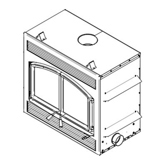
2.3 Measurements Solution 4.5 ZC Solution 4.5 ZC - Installation and Operation Manual... - Page 11 Solution 4.5 ZC - Installation and Operation Manual...
-
Page 12: Zone Heating And How To Make It Work For You
2.4 Zone Heating and How to make it work for you Your new SOLUTION 4.5 ZC wood fireplace is a space heater, which means it is intended to heat the area it is installed in, as well as spaces that connect to that area, although to a lower temperature. This is called zone heating and it is an increasingly popular way to heat homes or spaces within homes. -
Page 13: The Sbi Commitment To You And The Environment
Ceramic glass cannot be recycled in the same way as normal glass, so it should not be disposed of with your regular household products. Disposal at a landfill is recommended. Solution 4.5 ZC - Installation and Operation Manual... -
Page 14: Fuel
Old, leaky cast iron stoves wouldn’t hold a fire overnight unless they were fed large pieces of hardwood. That is no longer true. You can successfully heat your home by using the less desirable tree species and give the forest a break at the same time. Solution 4.5 ZC - Installation and Operation Manual... -
Page 15: Log Length
Firewood that is not dry enough to burn is the cause of most complaints about wood fireplaces. Continually burning green or unseasoned wood produces more creosote and involves lack of heat and dirty glass door. See Section 5: Maintaining your wood heating system for concerns about creosote. Solution 4.5 ZC - Installation and Operation Manual... -
Page 16: Judging Firewood Moisture Content
• wet, burn a piece; wet wood hisses and sizzles in the fire and dry wood does not. • You could buy a wood moisture meter to test your firewood. Solution 4.5 ZC - Installation and Operation Manual... -
Page 17: Manufactured Logs
BURNING THESE MATERIALS MAY RESULT IN RELEASE OF TOXIC FUMES OR RENDER THE HEATER INEFFECTIVE AND CAUSE SMOKE. IF THESE FUELS ARE BURNED, IT COULD CREATE A HIGHER CONCENTRATION OF CO THAN BURNING HARDWOOD. Solution 4.5 ZC - Installation and Operation Manual... -
Page 18: Operating Your Fireplace
A fire that starts fast produces less smoke and deposits less creosote in the chimney. Here are three popular and effective ways to start wood fires. Solution 4.5 ZC - Installation and Operation Manual... -
Page 19: Best Practice: The Top Down Fire
Gel starter may be used but only if there are no hot embers present. Use only in a cold firebox to start a fire. DO NOT USE FLAMMABLE LIQUIDS SUCH AS GASOLINE, NAPHTHA, FUEL OIL, MOTOR OIL, OR AEROSOLS TO START OR REKINDLE THE FIRE. Solution 4.5 ZC - Installation and Operation Manual... -
Page 20: Maintaining Wood Fires
There are two reasons for this raking of the coals. First, it concentrates them near where most of the combustion air enters the firebox and where they can ignite the new load quickly, and second, the charcoal Solution 4.5 ZC - Installation and Operation Manual... -
Page 21: Firing Each New Load Hot
If the flames diminish to the point of disappearing when you reduce the air supply, your wood can be too humid. If you have seasoned wood and use the air intake control properly, the flames should decrease, but remain strong and stable, even when operating at low combustion rate. Solution 4.5 ZC - Installation and Operation Manual... - Page 22 B-2 or B-1: Mid-Low or Low once the factory setting is reached. In the B position, it is also possible to close the air supply manually if a power failure occurs by pushing the small lever to the left. Solution 4.5 ZC - Installation and Operation Manual...
-
Page 23: Building Different Fires For Different Needs
Spaced them of around 6 inches. Let the door ajar until all the wood is on fire. Close the door. Solution 4.5 ZC - Installation and Operation Manual... - Page 24 For the medium burn rate, push the auxiliary air control toward the fireplace (see Section 4.3.5, position B-2). For the low burn rate, pull the auxiliary air control out (see Section 4.3.5, position B-1). Solution 4.5 ZC - Installation and Operation Manual...
-
Page 25: Maximum Burn Cycle Times
North-south loads break down more quickly, but much more wood can be loaded at a time. This makes north- south loading good for high output, long lasting fires for cold weather. Solution 4.5 ZC - Installation and Operation Manual... -
Page 26: Maintaining Your Wood Heating System
Visit your fireplace retailer to get the self-adhesive glass gasket and follow the instructions below for installation. Do not abuse the glass door by striking or slamming shut. Do not use the fireplace if the glass is broken. Solution 4.5 ZC - Installation and Operation Manual... -
Page 27: Door Adjustment
NOTE: At the end of each heating season, it is recommended to add a high temperature graphite paste on the threads of the door handle. This paste protects the threads from rust and prevents the accumulation of dust that can, over time, prevent the handle from rotating freely. Solution 4.5 ZC - Installation and Operation Manual... -
Page 28: Door Alignment
3/32” Allen key to free the adjustable hinge rods. Using a flat screwdriver, turn the adjustable hinge rods in the direction shown to adjust the doors. Tighten all door hinge pressure screws when they are at the desired positions. Solution 4.5 ZC - Installation and Operation Manual... -
Page 29: Replacing The Door Gaskets
Close the door and do not use the fireplace for 24 hours. Location Length (for one door) Dimensions Door frame 60" (153 cm) Round 5/8" (1,59 cm) Left door 18" Round 1/4" (0,64cm) Solution 4.5 ZC - Installation and Operation Manual... -
Page 30: Replacing The Door Glass
5.1.6 Replacing the Door Glass The glass used in the Solution 4.5 ZC is 4 mm thick of dimension 16.31" x 15.75" (41,4 cm x 40,0 cm) and tested to reach temperatures up to 1400º F. If the glass breaks, it must be replaced with one having the same specification. -
Page 31: Cleaning And Painting The Fireplace
Your new fireplace has the right characteristics to help you to burn clean fires with little or no smoke, resulting in less creosote in the chimney. Solution 4.5 ZC - Installation and Operation Manual... -
Page 32: How Often Should You Clean The Chimney
NOTE DO NOT EXPECT CHEMICAL CLEANERS TO KEEP YOUR CHIMNEY CLEAN. THE RAIN CAP CAN BE REMOVED FOR INSPECTION AND/OR CLEANING OF THE CHIMNEY. Solution 4.5 ZC - Installation and Operation Manual... -
Page 33: Fire Baffle Removal Prior To Cleaning The Chimney
5. Re-install the baffle, the air tubes and the rain cap. CAUTION OPERATION OF YOUR SOLUTION 4.5 ZC WITHOUT THE BAFFLE MAY CAUSE UNSAFE AND HAZARDOUS TEMPERATURE CONDITIONS AND WILL VOID THE WARRANTY. 5.2.4 Fire Baffle Removal Prior to Cleaning the Chimney Before starting to clean your chimney, we recommend that you remove the fire baffle to avoid creosote dust collection on top of the baffle. -
Page 34: Part B - Installation
DO NOT CONNECT THIS UNIT TO A CHIMNEY FLUE SERVING ANOTHER • APPLIANCE. THIS FIREPLACE HAS NOT BEEN TESTED TO BE INSTALLED IN A MOBILE HOME. • THIS FIREPLACE HAS NOT BEEN TESTED TO BE INSTALLED INSIDE A MASONRY • CHIMNEY. Solution 4.5 ZC - Installation and Operation Manual... -
Page 35: Regulations Covering Fireplace Installation
6.2 Regulations Covering Fireplace Installation When installed and operated as described in these instructions, the SOLUTION 4.5 ZC wood fireplace is suitable for use in residential installations. In Canada, the CSA B365 Installation Code for Solid Fuel Burning Appliances and Equipment and the CSA C22.1 Canadian National Electrical Code are to be followed in the absence of local code requirements. -
Page 36: Transportation Packaging
6.3.2 Transportation Packaging To facilitate transportation of the SOLUTION 4.5 ZC fireplace before installation, we have designed a transportation packaging that allows reducing the weight. The fireplace refractory panels are in a box you can carry separately. We suggest you install the refractory panels after the setting up of the fireplace. To install the refractory panels, see APPENDIX 5 - Refractory Slabs . -
Page 37: Hearth Extension Construction Options
Floor (under the fireplace): 0" Chimney: 2" (50 mm) 6.3.5 Hearth extension construction options The SOLUTION 4.5 ZC may be installed directly on the floor or on a raised combustible or non-combustible base. Installation can be done using one of the following options: Option... - Page 38 An 84" clearance between the fireplace base and the ceiling (A) must be respected. MINIMUM MEASUREMENTS 84" (2134 mm) 32" (813mm) 2" (51 mm) NOTE The floor under the fireplace should match or exceed the height of the floor protection. Solution 4.5 ZC - Installation and Operation Manual...
- Page 39 An 84" clearance between the fireplace base and the ceiling (A) must be respected. MINIMUM MEASUREMENTS 84" (2134 mm) 32" (813mm) Less than 8" (203 mm) 2" (51 mm) Solution 4.5 ZC - Installation and Operation Manual...
- Page 40 (not included). An 84" clearance between the fireplace base and the ceiling (A) must be respected. MINIMUM MEASUREMENTS 84" (2134 mm) 16" (406mm) More than 8" (203 mm) 2" (51 mm) Solution 4.5 ZC - Installation and Operation Manual...
- Page 41 An 84" clearance between the fireplace base and the ceiling (A) must be respected. MINIMUM MEASUREMENTS 84" (2134 mm) 20" (508 mm) Between 8" and 12" 2" (51 mm) Solution 4.5 ZC - Installation and Operation Manual...
- Page 42 An 84" clearance between the fireplace base and the ceiling (A) must be respected. MINIMUM MEASUREMENTS 84" (2134 mm) 16" (406 mm) 12" and more 2" (51 mm) Solution 4.5 ZC - Installation and Operation Manual...
- Page 43 * Information as reported by manufacturers and other resources. ** For a 1/8" thickness. You cannot «stack» horizontal still air to accumulate R-values; you must separate each layer of horizontal still air with another non-combustible material. Solution 4.5 ZC - Installation and Operation Manual...
-
Page 44: Minimum Heart Extension Requirements
Check local codes for approved alternatives. CAUTION DO NOT LEAVE CARPET UNDER THE FLOOR PROTECTION IN FRONT OF THE FIREPLACE. Solution 4.5 ZC - Installation and Operation Manual... -
Page 45: Framing Construction
FIREPLACE. THIS AREA MUST REMAIN EMPTY FOR A HEIGHT OF 84" (2.13 M) MEASURED FROM THE BASE OF THE FIREPLACE. LEGEND Combustible material allowed in this area Non-combustible material only in this area MEASUREMENTS 50 3/4" (128,8 cm) 26 7/8" (68,3 cm) Solution 4.5 ZC - Installation and Operation Manual... - Page 46 NOTE THIS FIREPLACE IS BUILT TO MAINTAIN A 1/2" GAP MINIMUM BETWEEN THE FIREPLACE AND THE FACEPLACE. IT IS RECOMMANDED TO HAVE THE NON- COMBUSTIBLE MATERIAL FLUSH WITH THE FIREPLACE. Solution 4.5 ZC - Installation and Operation Manual...
- Page 47 * The fresh air intake kit may be installed on the right side and at the bottom of the fireplace. Forced air distribution kit may be installed on either side of the fireplace. Solution 4.5 ZC - Installation and Operation Manual...
-
Page 48: Facing
THE FACEPLATE IS DESIGNED TO OVERLAP THE MATERIAL SURROUNDING THE FIREPLACE. IF THE MATERIAL IS THICKER, USE A FACEPLATE GAUGE FOR POSITIONING AND MAKE SURE THAT THE FACEPLATE CAN BE REMOVED AFTER IT HAS BEEN INSTALLED. Solution 4.5 ZC - Installation and Operation Manual... -
Page 49: Installation Of A Non-Combustible Shelf
It is possible to install a shelf but it must be made of non-combustible materials. It must be installed at, at least, 52" from the base of the fireplace. WARNING THE SHELF WILL BE HOT. DO NOT PUT COMBUSTIBLE MATERIALS ON THE SHELF. Solution 4.5 ZC - Installation and Operation Manual... -
Page 50: The Venting System
Solution 4.5 ZC - Installation and Operation Manual... -
Page 51: Chimney Installation Notes
The SOLUTION 4.5 ZC is listed only with chimney systems described in Table 3. A chimney venting a fireplace shall not vent any other appliance. - Page 52 For installations where more than one chimney is located in the same non-chase or within the same area, we suggest that their terminations be separated by at least 16" (410 mm) horizontally, and 18" (460 mm) vertically. This separation is to prevent smoke migrating from one chimney to another. Solution 4.5 ZC - Installation and Operation Manual...
- Page 53 18" 18" 457.2mm 457.2mm 18" 457.21mm 16" 16" 406.4mm 406.4mm Note: The chimney chase on the roof must be the same size as the flashing. Solution 4.5 ZC - Installation and Operation Manual...
-
Page 54: Chimney Installation Instructions
Always refer to the chimney manufacturer’s Installation manual to ensure a safe installation. Some non- illustrated parts may be required. 7.6.1 Examples of Typical Chimney Installation Straight Installation Exterior offset installation Connection to a masonry chimney Solution 4.5 ZC - Installation and Operation Manual... -
Page 55: Exterior Offset Installation
7.6.3 Installation Instructions WARNING THE STRUCTURAL INTEGRITY OF THE FLOOR, WALL, AND CEILING/ROOF MUST BE MAINTAINED. THE FLOOR AND WALLS BELOW THE ATTIC MUST BE INSULATED USING THE SAME INSULATION. Solution 4.5 ZC - Installation and Operation Manual... - Page 56 8. Install the chimney cap (G). 9. When a ventilated roof flashing is installed, precautions are to be taken not to caulk or seal the ventilating openings. Solution 4.5 ZC - Installation and Operation Manual...
-
Page 57: Offset Chimney Installation
MM) IN LENGTH (SEE IMAGE BELOW), IT SHALL BE CUT ABOVE THE LIFTING HOOKS WELDED TO THE INSIDE OF THE FLUE OUTLET SO THAT THE ANCHOR PLATE RESTS PERFECTLY ON TOP OF THE FIREPLACE. Solution 4.5 ZC - Installation and Operation Manual... - Page 58 TABLE 3 - LISTED CHIMNEYS FOR YOUR SOLUTION 4.5 ZC CHIMNEY INNER BRAND TYPE MANUFACTURER DIAMETER Olympia Chimney / Ventis 1" Solid Pack 8" (20 cm) SBI Venting Division SBI Venting Division Nexvent 1" Solid Pack 8" (20 cm) Olympia Chimney Rockford Chimney Systems 1"...
-
Page 59: Rafter Protection
Only one is required. Follow the chimney manufacturer’s installation instructions. In cold climate locations, it is recommended that you use the insulated wall radiation shield since it will maintain the home’s thermal barrier. INSULATED WALL RADIATION SHIELD GYPROCK INSULATED WALL Solution 4.5 ZC - Installation and Operation Manual... -
Page 60: Chimney Support Installation
FOR CONNECTION AT 30° OR 45° ANGLE (30° OR 45° IN CANADA AND 30° ONLY IN THE USA), A SPECIAL CONNECTOR MUST BE USED TO CONNECT THE LINER TO THE INSULATED CHIMNEY. VERIFY AVAILABILITY AND INSTALLATION INSTRUCTIONS FOR THIS CONNECTOR WITH THE CHIMNEY MANUFACTURER. Solution 4.5 ZC - Installation and Operation Manual... -
Page 61: Installation Instructions
Check the outdoor air duct for soot deposits when the venting system is cleaned and inspected. Solution 4.5 ZC - Installation and Operation Manual... -
Page 62: Appendix 1 - Hot Air Circulation Grille - Modern Style (Ac01378)
It is possible to connect a hot air circulation grille kit in the fireplace facing. This kit allows distributing heat to the room using natural convection. For the complete installation procedure, see the installation manual provided with the kit. You can also download this manual on the website. Solution 4.5 ZC - Installation and Operation Manual... -
Page 63: Appendix 2 - Forced Air Distribution Kit* (Va4460)
APPENDIX 2 - FORCED AIR DISTRIBUTION KIT* (VA4460) It is possible to connect a forced air distribution kit on either side of the SOLUTION 4.5 ZC. This kit allows distributing heat to another room up to 50 feet (15 m) of the fireplace. The insulated flexible pipe (not included in the kit) must be HVAC type pipe and must comply with ULC S110 and/or UL 181, Class 0 or Class 1 Standards and must withstand temperatures up to 250 °F. - Page 64 A 1" CLEARANCE TO COMBUSTIBLE MATERIALS (A) MUST BE LEFT AROUND THE TERMINATION GRILL. For the complete installation procedure, see the installation manual provided with the kit. You can also download this manual on the web site: www.valcourtinc.com Solution 4.5 ZC - Installation and Operation Manual...
-
Page 65: Appendix 3 - Blower Maintenance Or Replacement
2. With a short square head screwdriver, remove the 4 screws (C) holding in place the heat shield (B). 3. Remove and keep the heat shield (B) 4. Cut the Tie wrap (D). and the 4 screws (C). Solution 4.5 ZC - Installation and Operation Manual... - Page 66 5. Unplug the blower’s electric wires (F) and (G). 6. Lift the blower (E) located under the firebox towards the back. 7. Turn 90° to pull out. Repeat the steps in reverse order to reinstall the fan. Solution 4.5 ZC - Installation and Operation Manual...
-
Page 67: Appendix 4 - Installing The Fresh Air Intake Kit
Class 0 or Class 1 Standards and must withstand temperatures up to 250 °F. o The outside wall termination (E). o Adjustable clamps (2X) (C). Note: Only remove the knock-out that will be connected to the fresh air inlet. Solution 4.5 ZC - Installation and Operation Manual... - Page 68 1. Remove the knockout located on the right-hand side of your fireplace. 2. Install the 5" adapter included in your fireplace. Align the notch on the adaptor with the one on the fireplace and turn clockwise. Solution 4.5 ZC - Installation and Operation Manual...
- Page 69 Using a screwdriver, secure with four screws located in the user’s manual. Installing the block off plate will redirect air supply directly to the firebox instead of the area under the unit for combustion. Solution 4.5 ZC - Installation and Operation Manual...
- Page 70 For a better seal, you may also use aluminum tape. Wrap the tape around the joint between the flexible pipe and the air inlets. Carefully push the insulation and plastic cover back over the pipe. Fix the plastic in place using aluminum tape. Solution 4.5 ZC - Installation and Operation Manual...
-
Page 71: Appendix 5 - Refractory Slabs Installation (Ac02360)
(A & B). remove the slab holders (D) and the left and right refractory slabs (C). 3- Remove the rear refractory slab (E). To install new refractory slabs, follow the above steps in reverse. Solution 4.5 ZC - Installation and Operation Manual... -
Page 72: Appendix 6 - Installation Of Secondary Air Tubes And Baffle
1. Remove the inner ash retainer and the floor refractory 2. Using a power screwdriver and hex tip slab (A & B). 5/16", remove the slab holder (D) and the left refractory slab (C). Solution 4.5 ZC - Installation and Operation Manual... - Page 73 To remove the tubes use the above steps in reverse order. Note that secondary air tubes can be replaced without removing the baffle board. Important Notes: The air tubes are identified for placement as follows: Solution 4.5 ZC - Installation and Operation Manual...
-
Page 74: Appendix 7 - Air Control Snap Disc Replacement
(C). 3. Remove the 4 bolts (E) holding the access door (F) 4. Remove the thermodisc (G) by unscrewing the 2 with a 1/4" ratchet. screws holding it in place. (H) Solution 4.5 ZC - Installation and Operation Manual... -
Page 75: Appendix 8 - Electrical Wiring
The ground (green or skinned wire) must be attached to the fireplace metal frame. See appendix 9 for corresponding part numbers. Solution 4.5 ZC - Installation and Operation Manual... - Page 76 Solution 4.5 ZC - Installation and Operation Manual...
-
Page 77: Appendix 9 - Exploded Diagram And Parts List - Solution 4.5 Zc
APPENDIX 9 - Exploded Diagram and Parts List – SOLUTION 4.5 ZC Solution 4.5 ZC - Installation and Operation Manual... - Page 78 BLACK METAL SCREW #10 X 1/2" TYPE "A" PAN QUADREX 30485 WING NUT 1/4-20 X 1/2'' ZINC PLATTED 30117 SOCKET SET SCREW #10-32 X 1/4" 30586 HINGE PIN 30205 ZINC WASHER ID 13/32" X OD 13/16" Solution 4.5 ZC - Installation and Operation Manual...
- Page 79 REAR REFRACTORY BRICK PANEL 22028 LEFT REFRACTORY BRICK PANEL 22029 RIGHT REFRACTORY BRICK PANEL PL68762 FRONT SECONDARY AIR TUBE PL68763 CENTER FRONT SECONDARY AIR TUBE PL68764 REAR SECONDARY AIR TUBE PL68765 CENTER SECONDARY AIR TUBE Solution 4.5 ZC - Installation and Operation Manual...
- Page 80 ELECTRIC WIRE DOUBLE WHITE TEW 105°C 18 AWG 6'' ET 6'' 60378 ELECTRIC WIRE DOUBLE BLACK TEW 105°C 18 AWG 6'' ET 6'' 60278 ELECTRIC WIRE BLACK TEW 105°C 18 AWG 6'' 60291 ELECTRIC WIRE BLACK SEW2 200°C 18 AWG 12'' Solution 4.5 ZC - Installation and Operation Manual...
-
Page 81: Enerzone Limited Lifetime Warranty
ENERZONE LIMITED LIFETIME WARRANTY Solution 4.5 ZC - Installation and Operation Manual...
Need help?
Do you have a question about the SOLUTION 4.5 ZC and is the answer not in the manual?
Questions and answers