
Related Manuals for EOS EmoTouch 3 USA


Summary of Contents for EOS EmoTouch 3 USA
- Page 1 EmoTouch 3 USA Control Unit for Sauna Cabins Installation Instructions Made in Germany Druck-Nr.: 2902 5386 Stand: 13/2024...
-
Page 2: Documentation
Result of a step Table title Title of figure ≤ ≥ Less than or equal to, greater than or equal to Revision history Date Version Description 25 March 2024 01.00 First version EN-2 Installation Instructions - EmoTouch 3 USA... -
Page 3: Table Of Contents
Internal view of relay box..............EN-38 Circuit board assignment..............EN-39 EmoTouch 3 USA – 6–9 kW, 208 V connection diagram..EN-40 EmoTouch 3 USA – 6–9 kW, 240 V connection diagram..EN-41 EmoTouch 3 USA – 10–15 kW, 208 V connection diagram..EN-42 Connecting the control panel ............ - Page 4 Control lines and cabin addresses ..........EN-60 Programming of the cabin address ..........EN-62 Setting up a multi-cabin installation..........EN-63 7 General terms and conditions of service ........... EN-67 8 Disposal ......................EN-70 EN-4 Installation Instructions - EmoTouch 3 USA...
-
Page 5: General Safety Instructions
If the integrated battery in the control panel is not replaced cor- rectly, there is a risk of explosion which can lead to injury and fire. The integrated battery may only be replaced by a qualified spe- cialist. EmoTouch 3 USA - Installation Instructions EN-5... - Page 6 Similarly, excessive cold and extreme exposure to sunlight must be prevented. Protect the unit accordingly if there is an increased risk of me- chanical damage. EN-6 Installation Instructions - EmoTouch 3 USA...
-
Page 7: Operator Instruction
Spending time in a sauna cabin can lead to serious health risks or even death for persons with health impairments. Persons with health impairments who spend time in a sauna must consult a doctor before entering a sauna cabin. EmoTouch 3 USA - Installation Instructions EN-7... - Page 8 Avoid alcohol, drugs, and medications when you are using the sauna. Floor heating in the sauna cabin results in additional warming of the legs and can lead to health risks. EN-8 Installation Instructions - EmoTouch 3 USA...
- Page 9 Children and persons who have not received proper instruction must not clean or service the system. EmoTouch 3 USA - Installation Instructions EN-9...
-
Page 10: Safety Levels
For an overview of the standards that were observed during design and construction of the unit, please refer to the individual product's technical data sheet that can be downloaded from www.eos-sauna.com. Local regulations also apply to the installation and operation of heating, sauna, and steam room systems. -
Page 11: Identification
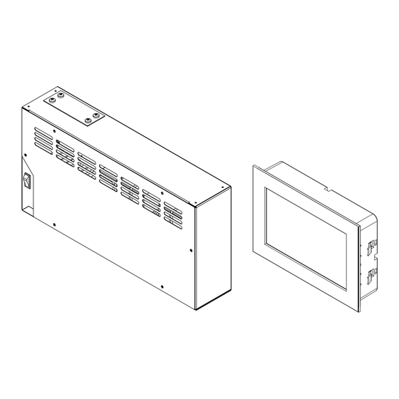
Finnish sauna mode Steamy hot air mode This documentation describes both models. Scope of delivery The following components are included in the EmoTouch 3 USA scope of delivery: A Relay box E 2x removal tool for control panel... -
Page 12: Nameplate
EOS-SAUNATECHNIK GmbH, Schneiderstriesch 1,35759 Driedorf A Name F Country of origin B Model G Manufacturer C Item number H Protection class D Operating voltage and maximum Manufacturing date switching output J Serial number E Safety temperature limiter EN-12 Installation Instructions - EmoTouch 3 USA... -
Page 13: Technical Data
See Connecting cables and fuses, EN-17 Fuses Color capacitive 7-inch touchscreen display in 16:9 format Display Based on ambient temperature: 30 °C–90 °C / 86 °F–194 °F Temperature control Digital two-point control Control characteristics EmoTouch 3 USA - Installation Instructions EN-13... - Page 14 See Connecting cables and fuses, EN-17 Pipe cross-sections Type A connection for memory card Other connections VAP1 and VAP2 with total of 3 kW Connection for vaporizer WM for water level sensor EN-14 Installation Instructions - EmoTouch 3 USA...
-
Page 15: Accessories (Optional
94.9081 SBM remote start 94.5782 Modular distributor RJ12 for connecting cable for control 2001.5298 panel and sauna bus Heating period limitation The heating period for the sauna heater is limited to one hour. EmoTouch 3 USA - Installation Instructions EN-15... -
Page 16: Intended Use
Identification Intended use EmoTouch 3 USA is designed to operate sauna heaters in sauna cabins. The relay box and control panel are intended only for mounting on the wall. EmoTouch 3 USA is suitable for residential and commercial sauna cab- ins. -
Page 17: Installation
AWG 12 40 A 6.0 kW 240 V AWG 12 AWG 12 15 A 7.5 kW 240 V AWG 12 AWG 12 20 A 9.0 kW 240 V AWG 12 AWG 12 20 A EmoTouch 3 USA - Installation Instructions EN-17... -
Page 18: Installation Work Inside The Cabin
The heater sensor controls the tem- perature in the sauna cabin. The heater sensor has a safety temperature limiter, which ensures that the temperature does not exceed the permitted temperature. EN-18 Installation Instructions - EmoTouch 3 USA... - Page 19 35 cm 19 cm 7.5 inch 13.8 inch A Cabins < 2 x 2 m / 6.6 x 6.6 ft B Cabins > 2 x 2 m / 6.6 x 6.6 ft EmoTouch 3 USA - Installation Instructions EN-19...
- Page 20 B Terminal 2 for safety temperature E Brown (sensor bus) limiter Connector pins for safety temperature limiter and sensor bus Screw the sensor housing to the cabin ceiling and place the housing cov- er in position. EN-20 Installation Instructions - EmoTouch 3 USA...
-
Page 21: Humidity Sensor
Do not install lighting in the emitting range of the heater. The lighting must conform to protection class IPX4 (splash- proof) and be resistant to ambient temperatures. Control line connection: Electrical installation, EN-34 EmoTouch 3 USA - Installation Instructions EN-21... -
Page 22: Relay Box
All lines should be routed before installing the relay box. Data lines must be routed and connected in such a way that they are not openly accessible. EN-22 Installation Instructions - EmoTouch 3 USA... -
Page 23: Installing The Relay Box
Installation Measurements for installation 445 mm / 18 inch Back of relay box 3.3.2 Installing the relay box Drill holes as required. Insert anchors into the drill holes if necessary. EmoTouch 3 USA - Installation Instructions EN-23... - Page 24 Installation Loosen the 6 screws on the cover. Remove the cover. Insert the cable glands into the openings and tighten with the nut. A Cable glands Loosen the 4 screws on the hood. EN-24 Installation Instructions - EmoTouch 3 USA...
- Page 25 Installation Remove the hood and the seal. A Hood B Seal Hook the relay box through the mounting holes and screw tight. EmoTouch 3 USA - Installation Instructions EN-25...
- Page 26 Once you have completed all installation work, you can connect the consumers and plug in the lines. 4.9 Safety temperature limiter, EN-44 4.11 Connecting the mains supply and units, EN-46 EN-26 Installation Instructions - EmoTouch 3 USA...
-
Page 27: Control Panel
Installation Control panel The housing of the EmoTouch 3 USA control panel is designed for mount- ing in the wall. If empty conduits for electrical installations are already pres- ent, this dictates the position of the control panel. 3.4.1 Requirements ... - Page 28 Mount the control panel far enough away from the area where steam is emitted and can spread. Mount the control panel on the hinge side of the door. EN-28 Installation Instructions - EmoTouch 3 USA...
-
Page 29: Mounting The Control Panel
Do not pull at the plug when routing the control line. Doing so could damage the line. Attach the taut wire only to the cable. The smaller RJ10 plug on the connecting cable must be routed to the control panel. EmoTouch 3 USA - Installation Instructions EN-29... - Page 30 When fixing the unit to the wall, ensure that the bottom of the unit is aligned properly. The side with the hole for the connecting cables and the slots for the removal tool must be facing downwards. EN-30 Installation Instructions - EmoTouch 3 USA...
- Page 31 Screw the screws into the holes on the 4 sides to fix the housing. Plugging in the lines Pull the control lines from the relay box through the ferrite ring twice. RJ10 RJ14 Slide the ferrite ring onto the bridge on the mounting plate. EmoTouch 3 USA - Installation Instructions EN-31...
- Page 32 Plug for multi-cabin connection, see 6.1 Configuration options, EN-55 Plugging in the control panel Place the control panel directly in front of the bottom piece. Ensure that it is aligned properly. Socket 1/2 must face downward. EN-32 Installation Instructions - EmoTouch 3 USA...
-
Page 33: Mounting The Fan
The fan is not included in the scope of delivery. Observe the separate installation instructions for the fan. Fan requirements Minimal output 5 W Maximum output 150 W Voltage 120 V 1 N AC Suitable for use in sauna cabins EmoTouch 3 USA - Installation Instructions EN-33... -
Page 34: Electrical Installation
Electrical installation must only be carried out by a qualified and licensed electrician. The unit must be connected to the power supply according to the circuit diagram and the terminal scheme. EmoTouch 3 USA - Installation Instructions EN-34... - Page 35 In a multi-cabin installation: Program the cabin address. See 6.3 Programming of the cabin address, EN-62 Configure additional settings at the control panel, e.g. target tempera- ture. See the operating instructions. EmoTouch 3 USA - Installation Instructions EN-35...
-
Page 36: Installation Examples
D Temperature sensor with safety temperature G Relay box limiter All wiring must be done in accordance with the National Electric Code and local building codes. All supply wire must be 90 °C copper. EN-36 Installation Instructions - EmoTouch 3 USA... - Page 37 D Temperature sensor with safety temperature G Relay box limiter All wiring must be done in accordance with the National Electric Code and local building codes. All supply wire must be 90 °C copper. EmoTouch 3 USA - Installation Instructions EN-37...
-
Page 38: Internal View Of Relay Box
F Heating circuit 2 (up to 15 kW or for 3 x vaporizers 240 V up to 9 kW) C Earth bar G Heating circuit 1 (up to 9 kW) Internal view of relay box EN-38 Installation Instructions - EmoTouch 3 USA... -
Page 39: Circuit Board Assignment
F Vaporizer connection (9 kW) K Terminal block for heating circuit 2 (up to 15 kW or for 240 V up to 9 kW) See the connection diagrams below for more information on connections. EmoTouch 3 USA - Installation Instructions EN-39... -
Page 40: Emotouch 3 Usa - 6-9 Kw, 208 V Connection Diagram
Electrical installation EmoTouch 3 USA – 6–9 kW, 208 V connection diagram SAFETY LIMITER HEATER Fuse, cable type 1, 2: see Connecting cables and fuses, EN-17. * The power rail must be able to accommodate a min. of 50 A. -
Page 41: Emotouch 3 Usa - 6-9 Kw, 240 V Connection Diagram
Electrical installation EmoTouch 3 USA – 6–9 kW, 240 V connection diagram SAFETY LIMITER HEATER Fuse, cable type 1, 2: see Connecting cables and fuses, EN-17. * The power rail must be able to accommodate a min. of 50 A. -
Page 42: Emotouch 3 Usa - 10-15 Kw, 208 V Connection Diagram
Electrical installation EmoTouch 3 USA – 10–15 kW, 208 V connection diagram SAFETY LIMITER HEATER Fuse, cable type 1, 2: see Connecting cables and fuses, EN-17. * The power rail must be able to accommodate a min. of 50 A. -
Page 43: Connecting The Control Panel
A Sauna bus (relay box) Guide the other end of the line (small RJ10 plug) to the control panel and connect it. Observe the relevant installation instructions. See 3.4.2 Mounting the control panel, EN-29 EmoTouch 3 USA - Installation Instructions EN-43... -
Page 44: Safety Temperature Limiter
Route the line through the openings at the top of the housing. HEATER SAUNA A Heater safety temperature lim- B Sauna safety temperature limiter iter Connect the STB cables from heater (A). Connect the STB cables from cabin (B). EN-44 Installation Instructions - EmoTouch 3 USA... -
Page 45: Connecting The Sensors
Route the lines through the openings at the top of the housing. Plug the plugs into one of the three sensor bus jacks (B) until they click into place. A Sauna bus (control panel) B Sensor bus (temperature sensor) EmoTouch 3 USA - Installation Instructions EN-45... -
Page 46: Connecting The Mains Supply And Units
Mains connection for vaporizer N, VAP1, VAP2 Single- or double-stage vaporizer (optional) Water shortage signal on vaporizer (optional) FL1, FN, FL2 Single- or double-stage fan LN, LL Cabin lighting 3, 4 Potential-free contact, max. 15 A EN-46 Installation Instructions - EmoTouch 3 USA... -
Page 47: Closing The Relay Box Housing
Housing cover is in place Preparing the vaporizer Open the water supply at the shut-off valve. Start the vaporizer. Please observe the installation and operating instructions for the connected heater with vaporizer. EmoTouch 3 USA - Installation Instructions EN-47... -
Page 48: Commissioning
All cabin settings are made via the control panel. All functions must be configured to commission the system. Add-on modules or accessories are detected after the unit is switched on again and their corresponding icons appear in the sub-menus. EmoTouch 3 USA - Installation Instructions EN-48... -
Page 49: User Interface Icons
5.1.1 User interface icons 01. June 2019 0:45:40 14:22:38 EmoTouch 3 USA control panel (example) The touch screen icons are displayed in various colors: Gray: Function button is inactive White: Function available or selected Green: Function button Confirm is selected ... -
Page 50: Switching On And Off
Set the time and confirm. Set the date and confirm. Specify and confirm the place of operation. European Union/CENELEC must be selected if the system is installed in countries under the jurisdiction of the CENELEC. EN-50 Installation Instructions - EmoTouch 3 USA... - Page 51 Confirm the confirmation prompt. If you do not confirm the safety system, the settings for the remote start module, the Web App WCI module and the timer are deactivat- Select the heater type and confirm. EmoTouch 3 USA - Installation Instructions EN-51...
- Page 52 After selecting the heater display, the selection of the connected modules is displayed again. If the installation is a multi-cabin installation, the skin, the heater dis- play and the modules for each cabin are set. EN-52 Installation Instructions - EmoTouch 3 USA...
-
Page 53: Troubleshooting
Bus connection plug not plugged in. Connect plug. Bus cable damaged. Replace bus cable. Unit not detected. Set unit address for the module. Other errors Software error. Restart unit. Contact technical support. EmoTouch 3 USA - Installation Instructions EN-53... -
Page 54: Installing Multiple Cabins
3 kW 1,5 kW 1,5 kW 500 W 400V 3N 230V 1N STEAM SAUNA S-BUS S-BUS max. 3 kW max. 9 kW 400V 3N 400V 3N LSG-IR Infrared relay box Sauna heater Vaporizer Modules EmoTouch 3 USA - Installation Instructions EN-54... -
Page 55: Configuration Options
6.1.2 Configuration 2 – 1 steam room and 4 additional cabins, EN-57. 6.1.3 Configuration 3 – 2 steam rooms, EN-58. 6.1.4 Configuration 4 – 2 steam room cabins and 4 additional cabins, EN-59. EmoTouch 3 USA - Installation Instructions EN-55... -
Page 56: Configuring 1-8 Sauna Cabins
All relay boxes are set by the factory to cabin address 1. See also the following figures: Jacks – sauna cabin relay box, EN-60 Jacks – EmoTouch 3 circuit board, EN-60 EN-56 Installation Instructions - EmoTouch 3 USA... -
Page 57: Configuration 2 - 1 Steam Room And 4 Additional Cabins
* Module = add-on modules, e.g. LSG-Sauna, LSG-IR, LSG-RB, etc. See also the following figures: Jacks – sauna cabin relay box, EN-60 Jacks – EmoTouch 3 circuit board, EN-60 EmoTouch 3 USA - Installation Instructions EN-57... -
Page 58: Configuration 3 - 2 Steam Rooms
Steam generator 3 Optional Steam generator 4 Optional See also the following figures: Jacks – sauna cabin relay box, EN-60 Jacks – EmoTouch 3 circuit board, EN-60 EN-58 Installation Instructions - EmoTouch 3 USA... -
Page 59: Configuration 4 - 2 Steam Room Cabins And 4 Additional Cabins
* Module = add-on modules, e.g. LSG-Sauna, LSG-IR, LSG-RB, etc. See also the figures for configuration 1: Jacks – sauna cabin relay box, EN-60 Jacks – EmoTouch 3 circuit board, EN-60 EmoTouch 3 USA - Installation Instructions EN-59... -
Page 60: Control Lines And Cabin Addresses
T 0.8A L 250V Jacks – sauna cabin relay box The relay boxes for steam room or IR cabins are described in detail in sepa- rate instructions. Jacks – EmoTouch 3 circuit board EN-60 Installation Instructions - EmoTouch 3 USA... - Page 61 Once the cabins with their custom cabin address (ID) are connected, the icon for the selected cabin is displayed in the footer. The number corresponds to the cabin currently selected (not the number of connected cabins). EmoTouch 3 USA - Installation Instructions EN-61...
-
Page 62: Programming Of The Cabin Address
2. See more about the various configurations: 6.1 Configuration options, EN-55 Programming button on the circuit board Programming button – relay box EN-62 Installation Instructions - EmoTouch 3 USA... -
Page 63: Setting Up A Multi-Cabin Installation
S-Bus connections on the circuit board of the EmoTouch 3 USA control panel. Observe the correct S-Bus connection sequence. Ensure the cabin address is correct. Plug in the S-Bus lines, EN-64 Programming addresses, EN-65 EmoTouch 3 USA - Installation Instructions EN-63... - Page 64 Plug the relay box for cabin 7 into jack #4 on the control panel. Plug the relay box for cabin 8 into jack #2 on the relay box for cabin 7. Once all lines have been plugged in, the cabin addresses must be deprogrammed. EN-64 Installation Instructions - EmoTouch 3 USA...
- Page 65 EmoTouch 3 control panel. Repeat programming if the cabin is not displayed. Please note that the address increases by one each time you press the programming button, e.g., from 4 to 5. EmoTouch 3 USA - Installation Instructions EN-65...
- Page 66 Plugging in the control panel, EN-32 Now you can make the settings for each cabin. 5.2 Setup during commissioning or after a reset, EN-50 For information on cabin settings, see the separate operating instructions. EN-66 Installation Instructions - EmoTouch 3 USA...
-
Page 67: General Terms And Conditions Of Service
The customer shall provide assistance free of charge to the manufacturer in rendering services. In the case of a warranty claim, the manufacturer shall provide spare parts necessary for servicing free of charge. EN-67 Installation Instructions - EmoTouch 3 USA... - Page 68 Only original spare parts may be used within the warranty period. Service visits made by third parties shall require a written order issued by our service department. EN-68 Installation Instructions - EmoTouch 3 USA...
- Page 69 The manufacturer's General Terms and Conditions of Business, in the ver- sion available at www.eos-sauna.com/agb, shall apply in addition to the foregoing terms and conditions of service. EmoTouch 3 USA - Installation Instructions...
-
Page 70: Disposal
Do not dispose of the unit with household waste. Packaging The packaging of the unit can be completely separated for disposal and recycled. The following materials are used in the packaging: Used paper, cardboard Plastic foil Foam material EmoTouch 3 USA - Installation Instructions EN-70... - Page 72 Store this address with the installation and operating instructions in a safe place. Please always provide us with nameplate data, such as model, item num- ber and serial number so we can provide fast and efficient support. Date of sale Stamp/retailer signature: © EOS Saunatechnik GmbH - All rights reserved.
Need help?
Do you have a question about the EmoTouch 3 USA and is the answer not in the manual?
Questions and answers