Table of Contents
Advertisement
Quick Links
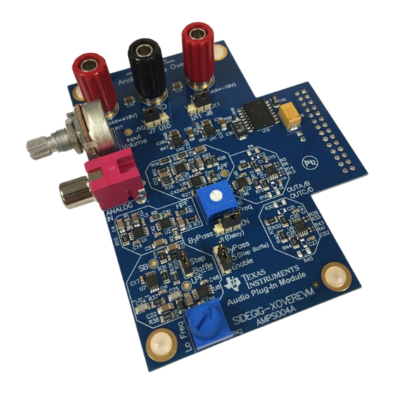
The TI Analog Crossover Audio Plug-in Module (SIDEGIG-XOVEREVM) turns TI Audio Class-D amplifier
EVM's into a high quality, two-way speaker amplifier. The plug-in module makes it easy to remove the
large and expensive passive crossover found in passive loudspeakers and create a bi-amped, two-way
system with improved efficiency and reduced size. The board features a tunable active crossover with a
high-pass filter, low-pass filter, baffle step, and delay to create two audio output signals for a tweeter and
woofer. There are many advantages of designing active speakers including well-matched and well-tuned
audio. This audio plug-in module plugs into an analog input Class-D audio evaluation module (EVM) with
an audio interface board (AIB) connector. This document provides information including setup, operation,
schematics, bill of materials (BOM) and printed-circuit board (PCB) layout. For questions and support, visit
the E2E forums: www.e2e.ti.com.
The main contents of this document are:
•
Hardware description
•
Hardware implementations
•
Design documents
SLAU742 – March 2018
Submit Documentation Feedback
Analog Crossover Audio Plug-In Module
Figure 1. Analog Crossover Audio Plug-In Module
Copyright © 2018, Texas Instruments Incorporated
User's Guide
SLAU742 – March 2018
Analog Crossover Audio Plug-In Module
1
Advertisement
Table of Contents

Related Manuals for Texas Instruments SIDEGIG-XOVEREVM


Summary of Contents for Texas Instruments SIDEGIG-XOVEREVM
- Page 1 SLAU742 – March 2018 Analog Crossover Audio Plug-In Module The TI Analog Crossover Audio Plug-in Module (SIDEGIG-XOVEREVM) turns TI Audio Class-D amplifier EVM’s into a high quality, two-way speaker amplifier. The plug-in module makes it easy to remove the large and expensive passive crossover found in passive loudspeakers and create a bi-amped, two-way system with improved efficiency and reduced size.
-
Page 2: Table Of Contents
Approximate Additional Time Delays With Corresponding Component Values and Approximate ................Frequency When Delay Decreases by 10% .......................... Trademarks All trademarks are the property of their respective owners. Analog Crossover Audio Plug-In Module SLAU742 – March 2018 Submit Documentation Feedback Copyright © 2018, Texas Instruments Incorporated... -
Page 3: Hardware Overview
Table 1. Plug-in Module Compatibility SUPPORTED CLASS-D SPEAKER PLUG-IN MODULE OUTPUT TYPE CLASS-D EVM INPUT TYPE CONFIGURATIONS 2x differential analog Analog 2x BTL SLAU742 – March 2018 Analog Crossover Audio Plug-In Module Submit Documentation Feedback Copyright © 2018, Texas Instruments Incorporated... -
Page 4: Class-D Output Drawings
Amplifier OUT-C OUT-D 2x BTL Figure 3. Class-D Output Drawings NOTE: Consult the Class-D EVM user’s guide for proper Class-D EVM configuration. Analog Crossover Audio Plug-In Module SLAU742 – March 2018 Submit Documentation Feedback Copyright © 2018, Texas Instruments Incorporated... -
Page 5: Aib Connector Pinout
Negative (–) analog input for low-frequency channel to audio Class-D EVM (IN_C and IN_D are Analog IN_D driven differentially by the Analog Crossover Plug- in Module) SLAU742 – March 2018 Analog Crossover Audio Plug-In Module Submit Documentation Feedback Copyright © 2018, Texas Instruments Incorporated... - Page 6 BTL); used for post-filter feedback Speaker-level output from audio Class-D EVM (SE AMP-IND or one side of BTL); used for post-filter feedback Analog Crossover Audio Plug-In Module SLAU742 – March 2018 Submit Documentation Feedback Copyright © 2018, Texas Instruments Incorporated...
-
Page 7: Analog Crossover Plug-In Module Setup
6. Plug in a standard RCA cable into the plug-in module. 7. Adjust the potentiometers for each channel to set the overall desired volume. SLAU742 – March 2018 Analog Crossover Audio Plug-In Module Submit Documentation Feedback Copyright © 2018, Texas Instruments Incorporated... -
Page 8: Connecting Audio Crossover Plug-In Module
This subsection describes the controls and use of the Analog Crossover Audio Plug-in Module. Figure 6 shows the Analog Crossover Plug-in Module controls. Figure 6. Analog Crossover Plug-in Module Controls Analog Crossover Audio Plug-In Module SLAU742 – March 2018 Submit Documentation Feedback Copyright © 2018, Texas Instruments Incorporated... -
Page 9: Low-Pass Filter Schematic
0.047µF 0.047µF OPA1602 Copyright © 2016, Texas Instruments Incorporated Figure 7. Low-Pass Filter Schematic Tthe low-pass filter circuit comprises two second-order Sallen-Key low-pass filters (U7B and U8A), which combine together to produce a fourth-order low-pass filter. R36 = R38, R37 = R39, C22 = C23, and C24 = C25;... -
Page 10: Low-Pass Filter Frequency Response
J6 (labeled “Baffle Step”), in which case the circuit becomes a unity-gain inverting amplifier. Figure 9 shows the schematic for the BSC circuit. Analog Crossover Audio Plug-In Module SLAU742 – March 2018 Submit Documentation Feedback Copyright © 2018, Texas Instruments Incorporated... -
Page 11: Baffle-Step Compensation (Bsc) Schematic
11.8k Step Baffle 11.8k 0.1µF 11.8k OPA1602 BAFFLE STEP COMPENSATION Copyright © 2016, Texas Instruments Incorporated Figure 9. Baffle-Step Compensation (BSC) Schematic The BSC circuit has the following transfer function shown in Equation æ ö sR C 31 19 ç... -
Page 12: High-Pass Filter Schematic
0.1µF 0.1µF 1.30k 1.30k HIGH-PASS FILTER Copyright © 2016, Texas Instruments Incorporated Figure 12. High-Pass Filter Schematic Using the component values as shown in the previous Figure 12 schematic, the filter has a cutoff frequency of approximately 1.8 kHz. The designer can modify the cutoff frequency if desired by changing one of the components on the first filter and the corresponding component on the second filter. -
Page 13: Cross Section Of Two-Way Loudspeaker Requiring Delay Compensation
Figure 14 shows a physical representation of this alignment difference. Figure 14. Cross Section of Two-Way Loudspeaker Requiring Delay Compensation SLAU742 – March 2018 Analog Crossover Audio Plug-In Module Submit Documentation Feedback Copyright © 2018, Texas Instruments Incorporated... -
Page 14: All-Pass Filter Schematic
0.1µF 1.00k ALL-PASS FILTER Copyright © 2016, Texas Instruments Incorporated Figure 15. All-Pass Filter Schematic The transfer function of the all-pass filter is a third-order function. The all-pass filter passes the signal with a constant gain. However, for the gain on the all-pass filter to stay at unity, R52 must equal R18 and R20 must equal R26. -
Page 15: Approximate Additional Time Delays With Corresponding Component Values And Approximate Frequency When Delay Decreases By
Volume Knob Control the master volume on the analog crossover module with R17, which is the potentiometer next to the RCA input jack. SLAU742 – March 2018 Analog Crossover Audio Plug-In Module Submit Documentation Feedback Copyright © 2018, Texas Instruments Incorporated... -
Page 16: Design Files
75.0k NR/SS 100 µF 0.01 µF 10.0k 10µF LT1054CDW 2.2 µF U12B TPS7A3001DRBR LT1054CDW OPA1602 OPA1602 Figure 17. SIDEGIG-XOVEREVM Schematic Page 1 Analog Crossover Audio Plug-In Module SLAU742 – March 2018 Submit Documentation Feedback Copyright © 2018, Texas Instruments Incorporated... -
Page 17: Sidegig-Xoverevm Schematic
0.047 µF ENABLE 0.047 µF OPA1602 100k BAFFLE STEP OPA1632DGNR COMPENSATION 180pF AMP-INC 220pF 7.50k 1.00k Figure 18. SIDEGIG-XOVEREVM Schematic Page 2 SLAU742 – March 2018 Analog Crossover Audio Plug-In Module Submit Documentation Feedback Copyright © 2018, Texas Instruments Incorporated... -
Page 18: Board Layouts
Design Files www.ti.com Board Layouts Figure 19 Figure 20 show the SIDEGIG-XOVEREVM layout images. Figure 19. Top Overlay Figure 20. Bottom Overlay Board Dimensions Figure 21 shows the SIDEGIG-XOVEREVM board dimensions. Figure 21. SIDEGIG-XOVEREVM Board Dimensions Analog Crossover Audio Plug-In Module SLAU742 –... -
Page 19: Bill Of Materials
RES, 11.8 k, 1%, 0.25 W, 1206 1206 RC1206FR-0711K8L Yageo America 10.0k RES, 10.0 k, 1%, 0.25 W, 1206 1206 RC1206FR-0710KL Yageo America SLAU742 – March 2018 Analog Crossover Audio Plug-In Module Submit Documentation Feedback Copyright © 2018, Texas Instruments Incorporated... - Page 20 RES, 7.50 k, 1%, 0.25 W, 1206 1206 RC1206FR-077K5L Yageo America Orange Miniature 5003 Keystone TP1, TP2, TP3, TP4 Test Point, Miniature, Orange, TH Testpoint Analog Crossover Audio Plug-In Module SLAU742 – March 2018 Submit Documentation Feedback Copyright © 2018, Texas Instruments Incorporated...
- Page 21 IMPORTANT NOTICE FOR TI DESIGN INFORMATION AND RESOURCES Texas Instruments Incorporated (‘TI”) technical, application or other design advice, services or information, including, but not limited to, reference designs and materials relating to evaluation modules, (collectively, “TI Resources”) are intended to assist designers who are developing applications that incorporate TI products;...
Need help?
Do you have a question about the SIDEGIG-XOVEREVM and is the answer not in the manual?
Questions and answers