
Related Manuals for Texas Instruments SmartRF06


Summary of Contents for Texas Instruments SmartRF06
- Page 1 User’s Guide SWRU321A – May 2013 SmartRF06 Evaluation Board User’s Guide SmartRF™ is a trademark of Texas Instruments...
-
Page 3: Table Of Contents
User’s Guide SWRU321A – May 2013 Table of Contents RF S ..............7 NSTALLING MART TUDIO AND DRIVERS 4.1.1 SmartRF Studio ......................... 7 4.1.2 FTDI USB driver ........................ 7 ................... 11 BSOLUTE AXIMUM ATINGS XDS100 ...................... 13 MULATOR 6.1.1 UART back channel ......................14 ...................... - Page 4 User’s Guide SWRU321A – May 2013 Figure 16 – SmartRF06EB I/O breakout overview ................ 23 Figure 17 – XDS100v3 Emulator Bypass Header (P408) ............. 24 Figure 18 – 20-pin ARM JTAG header (P409) ................25 Figure 19 – 10-pin ARM Cortex Debug header (P410) ..............26 Figure 20 –...
-
Page 5: Table 1 - Smartrf06Eb Features
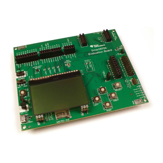
SWRU321A – May 2013 1 Introduction The SmartRF06 Evaluation Board (SmartRF06EB or simply EB) is the motherboard in development kits for Low Power RF ARM Cortex®-M based System on Chips from Texas Instruments. The board has a wide range of features, listed in Table 1 below. - Page 6 Master Out, Slave In (SPI signal) Not Applicable / Not Available Not Connected Radio Frequency Request to Send Receive System on Chip Serial Peripheral Interface Texas Instruments Test Point Transmit UART Universal Asynchronous Receive Transmit Universal Serial Bus Virtual COM Port Page 6/32...
-
Page 7: Installing Smartrf Studio And Usb Drivers
It also offers a flexible code export function of radio register settings for software developers. The latest version of SmartRF Studio can be downloaded from the Texas Instruments website [1], where you will also find a complete user manual. -
Page 8: Figure 1 - Driver Install: A) Update Driver, B) Specify Path To Ftdi Drivers
A “USB Serial Port” may be listed under “Other devices”, as seen in Figure 1a. Follow the same steps as for the “Texas Instruments XDS100v3” devices to install the VCP driver. When the drivers from <Studio install dir>\Drivers\ftdi is properly installed, you should see the USB Serial Port device be listed under “Ports (COM &... - Page 9 User’s Guide SWRU321A – May 2013 4.1.2.2 Install XSD100v3 UART back channel on Linux The ports on SmartRF06EB will typically be mounted as ttyUSB0 or ttyUSB1. The UART back channel is normally mounted as ttyUSB1. 1. Download the Linux drivers from [2]. 2.
-
Page 10: Figure 3 - Smartrf06Eb (Rev. 1.2.1) With Em Connected
User’s Guide SWRU321A – May 2013 5 Using the SmartRF06 Evaluation Board The SmartRF06EB is a flexible test and development platform that works together with RF Evaluation Modules from Texas Instruments. An Evaluation Module (EM) is a small RF module with RF chip, balun, matching filter, SMA antenna connector and I/O connectors. -
Page 11: Absolute Maximum Ratings
The SmartRF06EB can also be used as a debugger interface to the SoCs from IAR Embedded workbench for ARM or Code Composer Studio from Texas Instruments. For details on how to use the SmartRF06EB to debug external targets, see chapter 7. -
Page 12: Figure 4 - Smartrf06Eb Architecture
SmartRF06EB acts as the motherboard in development kits for ARM® Cortex™ based Low Power RF SoCs from Texas Instruments. The board has several user interfaces and connections to external interfaces, allowing fast prototyping and testing of both software and hardware. An overview of the SmartRF06EB architecture is found in Figure 4. -
Page 13: Xds100V3 Emulator
Figure 6 – SmartRF06EB revision 1.2.1 reverse side 6.1 XDS100v3 Emulator The XDS100v3 Emulator from Texas Instruments has cJTAG and regular JTAG support. cJTAG is a 2-pin extension to regular 4-pin JTAG. The XDS100v3 consists of a USB to JTAG chip from FTDI [2] and an FPGA to convert JTAG instructions to cJTAG format. -
Page 14: Uart Back Channel
User’s Guide SWRU321A – May 2013 In addition to regular debugging capabilities using cJTAG or JTAG, the XDS100v3 Emulator supports a UART backchannel over a USB Virtual COM Port (VCP) to the PC. The UART back channel supports flow control, 8-N-1 format and data rates up to 12Mbaud. Please see the XDS100v3 emulator product page [4] for detailed information about the emulator. -
Page 15: Usb Power
User’s Guide SWRU321A – May 2013 Figure 8 – Main power switch (P501) and source selection switch (P502) 6.2.1 USB Power When the SmartRF06EB is connected to a PC via a USB cable, it can draw power from the USB bus. -
Page 16: External Power Supply
User’s Guide SWRU321A – May 2013 Figure 10 – SmartRF06EB power source selection switch (P502) in “BAT” position 6.2.3 External Power Supply The SmartRF06EB can be powered using an external power supply. To power the mounted EM and the EB peripherals using an external power supply, the power source selection switch (S502) should be in “BAT”... -
Page 17: Power Domains
User’s Guide SWRU321A – May 2013 6.3 Power Domains The SmartRF06EB is divided into three power domains, described in detail in the following sections. The SmartRF06EB components, and what power domain they belong to, is shown in Figure 12 and Table 5 below. Mounted EM XDS domain 3.3 V domain... -
Page 18: Domain
User’s Guide SWRU321A – May 2013 The EM domain may be powered using various power sources; USB powered (regulated to 3.3 V), battery powered (regulated to 2.1 V or unregulated) and using an external power supply (regulated to 2.1 V or unregulated). When battery powered or powered by an external source, the EM power domain is by default regulated to 2.1 V using a step down converter. -
Page 19: Micro Sd Card Slot
User’s Guide SWRU321A – May 2013 Signal name Description Probe header EM pin LV_3.3V_EN 3.3 V domain enable signal RF1.15 (P407.1) RF1.15 LV_LCD_MODE LCD mode signal RF1.11 (P406.7) RF1.11 ¯¯¯¯¯¯¯¯¯¯¯¯¯¯ LV_LCD_RESET LCD reset signal (active low) RF1.13 (P406.9) RF1.13 ¯¯¯¯¯¯¯¯¯¯ LV_LCD_CS LCD Chip Select (active low) RF1.17 (P407.3) -
Page 20: Ambient Light Sensor
User’s Guide SWRU321A – May 2013 LV_SPI_MISO SPI MISO (acc. output) RF1.20_MISO (P407.5) RF1.20 Table 8 – Accelerometer signal connections 6.7 Ambient Light Sensor The SmartRF06EB has an analog SFH 5711 ambient light sensor (ALS) from Osram [7] that is available for the mounted EM via the EM connectors, enabling quick application development for demo use and prototyping. -
Page 21: Leds
User’s Guide SWRU321A – May 2013 6.9 LEDs 6.9.1 General Purpose LEDs The four LEDs D601, D602, D603, D604 can be controlled from the mounted EM and are suitable for demo use and debugging. The LEDs are active high. Table 11 shows an overview of I/O signals related to the LEDs. -
Page 22: Table 12 - Em Connector Rf1 Pin-Out
User’s Guide SWRU321A – May 2013 Probe Breakout EM pin Signal name Description header header RF1.1 Ground RF1.2 RF1.2 GPIO signal to EM board P406.1 P403.1-2 RF1.3 RF1.3_UART_CTS UART back channel / GPIO P412.4 P408.15-16 RF1.4 RF1.4 GPIO signal to EM board P406.2 P403.3-4 RF1.5... -
Page 23: Breakout Headers And Jumpers
User’s Guide SWRU321A – May 2013 6.11 Breakout Headers and Jumpers The SmartRF06EB has several breakout headers, giving access to all EM connector pins. An overview of the SmartRF06EB I/O breakout headers is given in Figure 16. Probe headers P406, P407, P411 and P412 give access to the I/O signals of the mounted EM. -
Page 24: Xds100V3 Emulator Bypass Headers
User’s Guide SWRU321A – May 2013 Probe CC2538EM Silk print EB signal name header connector P406 RF1.2 LV_LED_3 RF1.2 RF1.4 LV_LED_4 RF1.4 RF1.5 RF1.5 RF1.6 LV_BTN_LEFT RF1.6 RF1.8 LV_BTN_RIGHT RF1.8 RF1.10 LV_BTN_UP RF1.10 RF1.11 LV_LCD_MODE RF1.11 RF1.12 LV_BTN_DOWN RF1.12 RF1.13 ¯¯¯¯¯¯¯¯¯¯¯¯¯¯... -
Page 25: 20-Pin Arm Jtag Header
User’s Guide SWRU321A – May 2013 6.11.3 20-pin ARM JTAG Header The SmartRF06EB comes with a standard 20-pin ARM JTAG header [8] (Figure 18), enabling the user to debug an external target using the XDS100v3 Emulator. The pin-out of the ARM JTAG header is given in Table 15. -
Page 26: 10-Pin Arm Cortex Debug Header
User’s Guide SWRU321A – May 2013 6.11.4 10-pin ARM Cortex Debug Header The SmartRF06EB comes with a standard 10-pin ARM Cortex debug header [8] (Figure 19), enabling the user to debug an external target using the XDS100v3 Emulator. The ARM Cortex debug header is located near the right hand edge of the EB. -
Page 27: Current Measurement
User’s Guide SWRU321A – May 2013 6.12 Current Measurement The SmartRF06EB provides two options for easy measurements of the current consumption of a mounted EM. The following sections describe these two options in detail. 6.12.1 High-side current sensing The SmartRF06EB comes with a current sensing unit for measuring the current consumption of the mounted EM (Figure 20). -
Page 28: Figure 22 - Simplified Connection Diagram For Different Debugging Scenarios
User’s Guide SWRU321A – May 2013 7 Debugging an external target using SmartRF06EB You can easily use XDS100v3 Emulator onboard the SmartRF06EB to debug an external target. It is in this chapter assumed that the target is self-powered. When debugging an external, self-powered target using SmartRF06EB, make sure to remove the jumper from the current measurement header (J503) as shown in the second scenario of Figure 22. -
Page 29: 20-Pin Arm Jtag Header
User’s Guide SWRU321A – May 2013 7.1 20-pin ARM JTAG Header The SmartRF06EB has a standard 20-pin ARM JTAG header mounted on the right hand side (P409). Make sure all the jumpers on the XDS bypass header (P408) are mounted and that the jumper is removed from header J503. -
Page 30: Custom Strapping
User’s Guide SWRU321A – May 2013 7.3 Custom Strapping If the external board does not have a 20-pin ARM JTAG connector nor a 10-pin ARM Cortex connector, the needed signals may be strapped from the onboard XDS100v3 Emulator to the external target board. - Page 31 User’s Guide SWRU321A – May 2013 8 Frequently Asked Questions Nothing happens when I power up the evaluation board. Why? Make sure you have a power source connected to the EB. Verify that the power source selection switch (S502) is set correctly according to your power source. When powering the EB from either batteries or an external power source, S502 should be in “BAT”...
- Page 32 User’s Guide SWRU321A – May 2013 9 References [1] SmartRF Studio Product Page http://www.ti.com/tool/smartrftm-studio [2] FTDI USB Driver Page http://www.ftdichip.com [3] SmartRF Flash Programmer Product Page http://www.ti.com/tool/flash-programmer [4] XDS100 Emulator Product Page http://processors.wiki.ti.com/index.php/XDS100 [5] Electronic Assembly DOGM128-6 Datasheet http://www.lcd-module.com/eng/pdf/grafik/dogm128e.pdf [6] Bosch Sensortec BMA250 Datasheet http://ae-bst.resource.bosch.com/media/products/dokumente/bma250/bst-bma250- ds002-05.pdf [7] Osram SFH 5711...
- Page 33 User’s Guide SWRU321A – May 2013 Appendix A Schematics SmartRF06EB 1.2.1...
- Page 34 HOLE_3 XDS100v3 - FTDI XDS100v3 - FPGA LOW VOLTAGE EM INTERFACE/ HIGH VOLTAGE PERIPHERALS LEVEL SHIFTERS POWER SUPPLY PERIPHERALS CONTRACT NO. COMPANY NAME Texas Instruments APPROVALS DATE SmartRF06EB - Top Level DRAWN 12/07/12 SIZE FSCM NO. DWG NO. REV. CHECKED 13/07/12 1.2.1...
- Page 35 51 52 53 54 55 56 57 58 59 60 61 62 63 64 65 66 67 68 69 70 71 72 73 74 75 R_5K1_0402_J C_100N_0402_X5R_K_10 PRG_TDO Testpoint_Circle_40mils PRG_TMS Testpoint_Circle_40mils PRG_TDI Testpoint_Circle_40mils PRG_TCK Testpoint_Circle_40mils PRG_TRST Testpoint_Circle_40mils CONTRACT NO. COMPANY NAME Texas Instruments APPROVALS DATE SmartRF06EB - XDS100v3 - FPGA DRAWN 12/07/12 SIZE FSCM NO. DWG NO. REV. CHECKED 13/07/12 1.2.1 2(7) ISSUED...
- Page 36 BCBUS4 P3.3VXDS BCBUS5 LED_EL19-21SYGC EEPROM_DATA BCBUS6 BCBUS7 PWREN PWREN C_100N_0402_X5R_K_10 PWREN SUSPEND SUSPEND CONTRACT NO. COMPANY NAME Texas Instruments APPROVALS DATE SmartRF06EB - XDS100v3 - FTDI DRAWN 12/07/12 SIZE FSCM NO. DWG NO. REV. CHECKED 13/07/12 1.2.1 ISSUED 13/07/12 3(7)
- Page 37 Saturation point for INA216 LV_BTN_RESET ----------------------------- Vout_max = LO_VDD (2.1V to 3.6V) Vin_max = LO_VDD / 100 = 21mV to 36mV Ishunt_max = 140mA to 240mA CONTRACT NO. COMPANY NAME Texas Instruments EM Interface / APPROVALS DATE SmartRF06EB - Level Shifters DRAWN 12/07/12 SIZE FSCM NO.
- Page 38 2.1V FOR EM and LV PERIPHERALS VOUT TPS73533 USB TO 1.5V (FPGA) P3.3VXDS +1.5V V_USB TP19 TLV70015 VOUT TLV70015 SUSPEND CONTRACT NO. COMPANY NAME Texas Instruments APPROVALS DATE SmartRF06EB - Power Supply DRAWN 12/07/12 SIZE FSCM NO. DWG NO. REV. CHECKED 13/07/12 1.2.1...
- Page 39 C601 HI_VDD HI_VDD HI_VDD SIP_SOCKET_SMD_1X20_2.54MM INSERT: 1 pc SIP_SOCKET_SMD_1X20_2.54MM 2 pc SIP_SOCKET_SMD_1X3_2.54MM DOGM128W-6_NO_CON LCD1 SIP_SOCKET_SMD_1X3_2.54MM SIP_SOCKET_SMD_1X3_2.54MM CONTRACT NO. COMPANY NAME Texas Instruments APPROVALS DATE High Voltage SmartRF06EB - Peripherals DRAWN 12/07/12 SIZE FSCM NO. DWG NO. REV. CHECKED 13/07/12 1.2.1...
- Page 40 S605 C_100N_0402_X5R_K_10 LV_LED_3 LV_BTN_DOWN PUSH_BUTTON_SKRAAK LED_EL19-21SYGC R_680_0402_G R609 RED-ORANGE D604 LV_LED_4 LED_EL19-21SURC R_680_0402_G R610 CONTRACT NO. COMPANY NAME Texas Instruments APPROVALS DATE Low Voltage SmartRF06EB - Peripherals DRAWN 12/07/12 SIZE FSCM NO. DWG NO. REV. CHECKED 13/07/12 1.2.1 7(7) ISSUED...
- Page 41 Any exceptions to this are strictly prohibited and unauthorized by Texas Instruments unless user has obtained appropriate experimental/development licenses from local regulatory authorities, which is responsibility of user including its acceptable authorization.
- Page 42 FCC Interference Statement for Class B EVM devices This equipment has been tested and found to comply with the limits for a Class B digital device, pursuant to part 15 of the FCC Rules. These limits are designed to provide reasonable protection against harmful interference in a residential installation. This equipment generates, uses and can radiate radio frequency energy and, if not installed and used in accordance with the instructions, may cause harmful interference to radio communications.
- Page 43 Also, please do not transfer this product, unless you give the same notice above to the transferee. Please note that if you could not follow the instructions above, you will be subject to penalties of Radio Law of Japan. Texas Instruments Japan Limited (address) 24-1, Nishi-Shinjuku 6 chome, Shinjuku-ku, Tokyo, Japan http://www.tij.co.jp...
- Page 44 FDA Class III or similar classification, then you must specifically notify TI of such intent and enter into a separate Assurance and Indemnity Agreement. Mailing Address: Texas Instruments, Post Office Box 655303, Dallas, Texas 75265 Copyright © 2013, Texas Instruments Incorporated...
- Page 45 IMPORTANT NOTICE Texas Instruments Incorporated and its subsidiaries (TI) reserve the right to make corrections, enhancements, improvements and other changes to its semiconductor products and services per JESD46, latest issue, and to discontinue any product or service per JESD48, latest issue.
- Page 46 Компания «ЭлектроПласт» предлагает заключение долгосрочных отношений при поставках импортных электронных компонентов на взаимовыгодных условиях! Наши преимущества: Оперативные поставки широкого спектра электронных компонентов отечественного и импортного производства напрямую от производителей и с крупнейших мировых складов; Поставка более 17-ти миллионов наименований электронных компонентов; ...
Need help?
Do you have a question about the SmartRF06 and is the answer not in the manual?
Questions and answers