Table of Contents
Advertisement
Quick Links
www.ti.com
User's Guide
SN6507DGQEVM Low-Emissions 500 mA Push-Pull
Transformer Driver for Isolated Power Supplies
Evaluation Module
This user's guide describes the evaluation module (EVM) for TI's SN6507 push-pull isolation transformer driver.
This EVM helps designers analyze and evaluate performance of the SN6507 device for quick development of
isolated power supplies.
In addition to the SN6507 device, this EVM contains a small form-factor transformer, simple rectifier circuit,
voltage regulator, and various adjustable options. These combinations simulate a complete isolated power
supply system suitable for many applications.
1
Introduction.............................................................................................................................................................................2
2
Overview..................................................................................................................................................................................2
Operation......................................................................................................................................................4
Options...................................................................................................................................................5
5 Bill of Materials.......................................................................................................................................................................
6 EVM Schematic and PCB.....................................................................................................................................................
Figure 2-1. SN6507DGQEVM Radiated Emissions Sweep at Full Load per CISPR 32 Class B................................................
Figure 4-1. SN6507 Pinout..........................................................................................................................................................
Figure 4-2. SN6507DGQEVM Top View......................................................................................................................................
Table 4-1. LM317A (U1) Resistor Values for Common Regulated Output Voltages....................................................................
Trademarks
All trademarks are the property of their respective owners.
SLLU346 - APRIL 2022
Submit Document Feedback
ABSTRACT
Table of Contents
List of Figures
Operation...........................................................................................................................4
Schematic..................................................................................................................................10
Layout.........................................................................................................................11
Layout...................................................................................................................12
List of Tables
Configurations..................................................................................................................7
Materials..............................................................................................................................8
Copyright © 2022 Texas Instruments Incorporated
SN6507DGQEVM Low-Emissions 500 mA Push-Pull Transformer Driver for
Isolated Power Supplies Evaluation Module
Table of Contents
8
10
3
5
5
6
1
Advertisement
Table of Contents

Related Manuals for Texas Instruments SN6507DGQEVM


Summary of Contents for Texas Instruments SN6507DGQEVM
-
Page 1: Table Of Contents
Options..............................5 5 Bill of Materials..................................6 EVM Schematic and PCB..............................List of Figures Figure 2-1. SN6507DGQEVM Radiated Emissions Sweep at Full Load per CISPR 32 Class B..........Figure 3-1. Basic SN6507DGQEVM Operation...........................4 Figure 4-1. SN6507 Pinout................................Figure 4-2. SN6507DGQEVM Top View............................ -
Page 2: Introduction
J4. Once enabled, the regulator outputs a stable, regulated +12-VDC output by default that can also be used to drive up to 500 mA load circuits. As configured by default, the SN6507DGQEVM complies with the CISPR 32 Class B radiated emissions standard, as shown by the measurement in Figure 2-1. -
Page 3: Figure 2-1. Sn6507Dgqevm Radiated Emissions Sweep At Full Load Per Cispr 32 Class B
Overview Figure 2-1. SN6507DGQEVM Radiated Emissions Sweep at Full Load per CISPR 32 Class B Use this EVM to evaluate electrical and timing parameters of the SN6507 device in different configurations. Apply power to evaluate performance characteristics such as enable delay, rise and fall times, soft-start duration, and power consumption for different load conditions. -
Page 4: Evm Setup And Operation
Both grounds of the EVM may be shorted together for evaluation. In practice, shorting the non- isolated and isolated grounds would bypass the isolation barrier and is not recommended. Figure 3-1. Basic SN6507DGQEVM Operation SN6507DGQEVM Low-Emissions 500 mA Push-Pull Transformer Driver for SLLU346 – APRIL 2022 Isolated Power Supplies Evaluation Module Submit Document Feedback Copyright ©... -
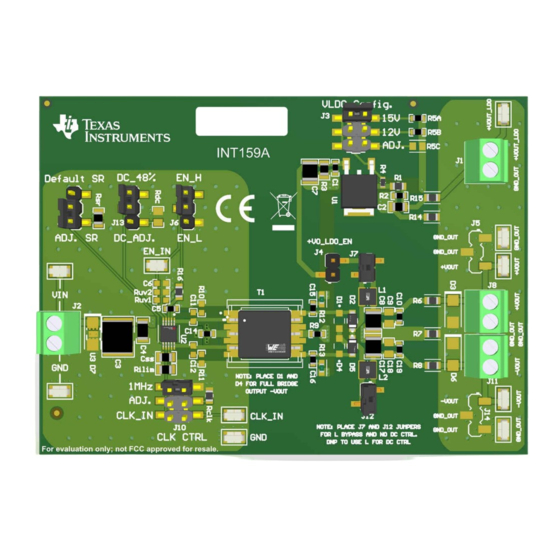
Page 5: Evm Configuration Options
EN/UVLO Figure 4-1. SN6507 Pinout The SN6507DGQEVM is designed for flexibility in evaluation of the SN6507 device by providing placeholder options for several external components. The SN6507 pin-configurable options, snubber circuit components, full-bridge output configurations, LDO output, and the isolation transformer itself may all be adjusted using component-footprint and jumper provisions on this EVM. -
Page 6: Table 4-1. Lm317A (U1) Resistor Values For Common Regulated Output Voltages
Table 4-1. LM317A (U1) Resistor Values for Common Regulated Output Voltages Desired V R4 value (Ω) R5C value (Ω) 2044 2615 4326 SN6507DGQEVM Low-Emissions 500 mA Push-Pull Transformer Driver for SLLU346 – APRIL 2022 Isolated Power Supplies Evaluation Module Submit Document Feedback Copyright © 2022 Texas Instruments Incorporated... -
Page 7: Table 4-2. Sn6507Dgqevm Jumper Configurations
Desired V R4 value (Ω) R5C value (Ω) 6609 Jumper configurations: Table 4-2 details the jumper configuration information of the SN6507DGQEVM. Table 4-2. SN6507DGQEVM Jumper Configurations Connection Label Function 15 V, 12 V, ADJ. Connect pins 1-2, 2-3, or 5-6 of J3 to select the desired regulated output voltage of either 15... -
Page 8: Bill Of Materials
(2012 Metric) Automotive AEC-Q200 Thick Film Electronics RES, 10 k, 5%, 0.1 W, 0603 RC0603JR-0710KL Yageo SN6507DGQEVM Low-Emissions 500 mA Push-Pull Transformer Driver for Isolated Power Supplies SLLU346 – APRIL 2022 Evaluation Module Submit Document Feedback Copyright © 2022 Texas Instruments Incorporated... - Page 9 Low-Noise 36 V Push-Pull Transformer Driver with PowerPAD10 SN6507DGQ Texas Instruments Duty Cycle Control for Isolated Power Supplies SLLU346 – APRIL 2022 SN6507DGQEVM Low-Emissions 500 mA Push-Pull Transformer Driver for Isolated Power Supplies Submit Document Feedback Evaluation Module Copyright © 2022 Texas Instruments Incorporated...
-
Page 10: Evm Schematic And Pcb
Rclk, Rsr, Rdc, Rilim, Css can be adjusted per DC adjust. SN6507 datasheet 50.5k Figure 6-1. SN6507DGQEVM Schematic SN6507DGQEVM Low-Emissions 500 mA Push-Pull Transformer Driver for Isolated Power Supplies SLLU346 – APRIL 2022 Evaluation Module Submit Document Feedback Copyright © 2022 Texas Instruments Incorporated... -
Page 11: Figure 6-2. Sn6507Dgqevm Top Pcb Layout
Bill of Materials Figure 6-2. SN6507DGQEVM Top PCB Layout SLLU346 – APRIL 2022 SN6507DGQEVM Low-Emissions 500 mA Push-Pull Transformer Driver for Isolated Power Supplies Submit Document Feedback Evaluation Module Copyright © 2022 Texas Instruments Incorporated... -
Page 12: Figure 6-3. Sn6507Dgqevm Bottom Pcb
Bill of Materials www.ti.com Figure 6-3. SN6507DGQEVM Bottom PCB Layout SN6507DGQEVM Low-Emissions 500 mA Push-Pull Transformer Driver for Isolated Power Supplies SLLU346 – APRIL 2022 Evaluation Module Submit Document Feedback Copyright © 2022 Texas Instruments Incorporated... - Page 13 STANDARD TERMS FOR EVALUATION MODULES Delivery: TI delivers TI evaluation boards, kits, or modules, including any accompanying demonstration software, components, and/or documentation which may be provided together or separately (collectively, an “EVM” or “EVMs”) to the User (“User”) in accordance with the terms set forth herein.
- Page 14 www.ti.com Regulatory Notices: 3.1 United States 3.1.1 Notice applicable to EVMs not FCC-Approved: FCC NOTICE: This kit is designed to allow product developers to evaluate electronic components, circuitry, or software associated with the kit to determine whether to incorporate such items in a finished product and software developers to write software applications for use with the end product.
- Page 15 www.ti.com Concernant les EVMs avec antennes détachables Conformément à la réglementation d'Industrie Canada, le présent émetteur radio peut fonctionner avec une antenne d'un type et d'un gain maximal (ou inférieur) approuvé pour l'émetteur par Industrie Canada. Dans le but de réduire les risques de brouillage radioélectrique à...
- Page 16 www.ti.com EVM Use Restrictions and Warnings: 4.1 EVMS ARE NOT FOR USE IN FUNCTIONAL SAFETY AND/OR SAFETY CRITICAL EVALUATIONS, INCLUDING BUT NOT LIMITED TO EVALUATIONS OF LIFE SUPPORT APPLICATIONS. 4.2 User must read and apply the user guide and other available documentation provided by TI regarding the EVM prior to handling or using the EVM, including without limitation any warning or restriction notices.
- Page 17 Notwithstanding the foregoing, any judgment may be enforced in any United States or foreign court, and TI may seek injunctive relief in any United States or foreign court. Mailing Address: Texas Instruments, Post Office Box 655303, Dallas, Texas 75265 Copyright © 2019, Texas Instruments Incorporated...
- Page 18 TI products. TI’s provision of these resources does not expand or otherwise alter TI’s applicable warranties or warranty disclaimers for TI products. TI objects to and rejects any additional or different terms you may have proposed. IMPORTANT NOTICE Mailing Address: Texas Instruments, Post Office Box 655303, Dallas, Texas 75265 Copyright © 2022, Texas Instruments Incorporated...
Need help?
Do you have a question about the SN6507DGQEVM and is the answer not in the manual?
Questions and answers