Ultimaker S3 Repair Instructions
S-line electronics with dongle
Hide thumbs
Also See for S3:
- User manual ,
- Quick start manual (88 pages) ,
- Installation and user manual (33 pages)
Advertisement
Quick Links
Repair instructions
S-line electronics (with dongle)
Version
EN-V1.0-12/2022
Products
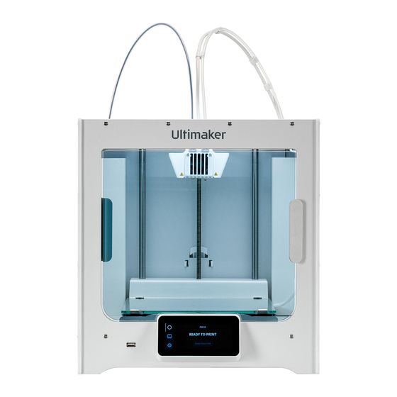
Ultimaker S3, Ultimaker S5 R2
Introduction
Due to Chipageddon, some changes were implemented to the S-line electronics. The SOM board
now no longer has integrated Ethernet functionality, so the addition of a separate USB dongle is
required. The Wi-Fi connector has changed, which means the Wi-Fi antenna also must be
replaced
Requirements
Tools
ESD prevention supplies
•
Torque screwdriver (0.5 Nm)
•
2.0 mm hex bit
•
2.0 mm hex screwdriver
•
Safety plug (recommended)
•
Door fixation tools (recommended)
•
Notes
Caution: Ultimaker S-line printers are powered by mains voltage, which is hazardous
when touched. Turn off the printer and disconnect the power cable before starting this
procedure.
Caution: This repair involves working with or exposing sensitive electronic components.
Take ESD precautions before starting this procedure.
Note: When replacing this complete electronics assembly, the USB dongle must be
installed to ensure Ethernet functionality. Due to the different sized connector on the
Wi-Fi module, also replace the Wi-Fi antenna or transfer the old Wi-Fi module to the new
mainboard.
Tip: All orientations are as seen from the front in the upright orientation, unless specified
otherwise.
Parts
1x 234906 – S-line electronics assembly,
including the following parts
SMARC Mainboard + SOM + Wi-Fi module
•
assembly
USB dongle
•
Wi-Fi antenna
•
Advertisement

Related Manuals for Ultimaker S3


Summary of Contents for Ultimaker S3
- Page 1 Wi-Fi antenna • Notes Caution: Ultimaker S-line printers are powered by mains voltage, which is hazardous when touched. Turn off the printer and disconnect the power cable before starting this procedure. Caution: This repair involves working with or exposing sensitive electronic components.
- Page 2 Disassembly Secure the door(s). Place the door fixation tools between the glass doors (Ultimaker S5) or between the door and front panel (Ultimaker S3) to keep the door(s) in place. Tip: This prevents the door(s) from falling open when handling the printer.
- Page 3 Reassembly Place the thermal conductive pads. Align the two thermal conductive pads with the markings on the bottom panel. Firmly push them so they stick to the panel. Tip: If the thermal conductive pads remained stuck to the bottom panel, skip this step. Ensure they are firmly stuck before proceeding.
- Page 4 Place the USB dongle. Stick the USB dongle to the bottom panel (EMC plate) in the location as indicated below. Please note the correct orientation Ultimaker S3 Ultimaker S5 R2 Place the dongle straight against the power Place the dongle at an angle in the middle of...
- Page 5 Ultimaker S3/S5-R2 Electronics overview Speaker LED strip Only if present. Do not connect until placing the bottom cover back. HDMI USB Dongle (front panel) Camera Wi-Fi antenna Not used. Connect the Ethernet to USB Ethernet dongle Flow sensor Flow sensor...
- Page 6 Download the correct article number file from this page. Ensure to select the correct printer type (Ultimaker S3 or Ultimaker S5) and the version with the USB dongle. Unzip the file. Do not make any changes to the file or file name. Prepare the USB drive The USB drive does not need to be empty, but ensure no other provisioning files are on the USB drive.
- Page 7 Appendix Transfer the Wi-Fi module The Wi-Fi module on the new electronics assembly has a different sized connector. For this reason, it is not compatible with the older Wi-Fi antenna. If you do not want to replace the Wi-Fi antenna and Wi-Fi module, you can transfer the old Wi-Fi module from the old mainboard to the new board.
Need help?
Do you have a question about the S3 and is the answer not in the manual?
Questions and answers