Table of Contents
Advertisement
Quick Links
www.ti.com
EVM User's Guide: LMX2624SPEVM
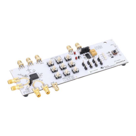
LMX2624-SP Evaluation Module With 26GHz Space Grade
Synthesizer
Description
LMX2624SPEVM is used to evaluate the performance
of the LMX2624-SP device. This device is a
space grade RF synthesizer in 10mm x 10mm
64-pin plastic package. LMX2624-SP is able to
generate continuous wave signal up to 26GHz.
LMX2624SPEVM evaluation module provides all the
hardware interface to enable users to quickly evaluate
and develop with the LMX2624-SP RF synthesizer.
Get Started
1. Order the EVM, LMX2624SPEVM.
2. Download the latest programming GUI,
3. Download the PLL simulation tool,
Sim.
4. Learn more about VCO calibration, SNAA336.
5. Ping-pong architecture overview, SNAA357.
Features
•
Up to 15.24GHz direct VCO output and 26GHz
VCO doubler output at both output ports
SNAU308 – NOVEMBER 2024
Submit Document Feedback
•
JESD204 SYSREF clock generation and repeater
mode operation
•
Support synchronization of output phase across
multiple devices
•
Onboard USB interface for SPI control
•
Support pin control operation without SPI
programming
Applications
•
Space communications
•
Space radar systems
•
Phased array antennas and beam forming
•
High-speed data converter clocking (supports
JESD204B)
TICS
Pro.
PLLatinum
LMX2624-SP Evaluation Module With 26GHz Space Grade Synthesizer
Copyright © 2024 Texas Instruments Incorporated
Description
1
Advertisement
Table of Contents

Related Manuals for Texas Instruments LMX2624-SP


Summary of Contents for Texas Instruments LMX2624-SP
- Page 1 LMX2624SPEVM is used to evaluate the performance • Support synchronization of output phase across of the LMX2624-SP device. This device is a multiple devices space grade RF synthesizer in 10mm x 10mm • Onboard USB interface for SPI control 64-pin plastic package.
-
Page 2: Kit Contents
Configuration of LMX2624-SP is made through SPI programming. LMX2624-SP can operate without SPI programming via pin strapping in Pin mode. This device is fabricated in Texas Instruments' advanced BiCMOS process and is available in a 64-lead 10mm x 10mm QFP plastic package. -
Page 3: Jumper Information
When LDO is bypassed (EVM default configuration). Apply 3.3V to VCCIN SMA connector. Acceptable supply voltage range is 3.2V to 3.4V. SNAU308 – NOVEMBER 2024 LMX2624-SP Evaluation Module With 26GHz Space Grade Synthesizer Submit Document Feedback Copyright © 2024 Texas Instruments Incorporated... -
Page 4: Reference Clock
Test point Designator Property VCCIN 3.3V (LDO bypassed) 3.6V to 4V (use onboard LDO) VBIAS 5V (use onboard LDO) 3.3V LMX2624-SP Evaluation Module With 26GHz Space Grade Synthesizer SNAU308 – NOVEMBER 2024 Submit Document Feedback Copyright © 2024 Texas Instruments Incorporated... -
Page 5: Software Installation
Download and install TICS Pro software from www.ti.com/tool/ticspro-sw. 3.3 USB2ANY Interface The on-board USB2ANY interface provides a bridge between TICS Pro software and the LMX2624-SP device. When the on-board USB2ANY controller is first connected to a PC, or if the firmware revision for the controller does not match with the version used by TICS Pro, a firmware update to the controller is required. - Page 6 9. Click the Identify button, the LED in the USB2ANY interface flashes. Figure 3-6. Identify USB2ANY Controller 10. Now, the USB2ANY is ready to use. Click the Close button to close the window. LMX2624-SP Evaluation Module With 26GHz Space Grade Synthesizer SNAU308 – NOVEMBER 2024 Submit Document Feedback...
- Page 7 2. The "ReadMe" page loads. Please take a minute to read the content to have an overview of the GUI. 3. Go to Default Configuration → EVM Default Mode. Figure 4-2. Default Mode 4. Go to USB Communications → Write All Registers to write all the registers to LMX2624-SP. 4.2 Performance Data and Results 4.2.1 RF Output With EVM Default Mode configuration, VCO frequency is 12GHz, RFoutA output is 6GHz.
- Page 8 To complete the doubler calibration, set FCAL_DBLR_EN = 1 and click the Calibrate VCO button once (this programs R0). Figure 4-6. VCO Doubler Calibration Figure 4-7. VCO Doubler Output LMX2624-SP Evaluation Module With 26GHz Space Grade Synthesizer SNAU308 – NOVEMBER 2024 Submit Document Feedback Copyright © 2024 Texas Instruments Incorporated...
- Page 9 Figure 4-10. Output Mute Control The response time of mute control using the hardware pin is very fast, typical value is 10ns. SNAU308 – NOVEMBER 2024 LMX2624-SP Evaluation Module With 26GHz Space Grade Synthesizer Submit Document Feedback Copyright © 2024 Texas Instruments Incorporated...
- Page 10 Whenever the VCO frequency is change, a VCO calibration is required to select the right VCO core and band for the PLL to lock. In LMX2624-SP, there are 7 VCO cores and each core has 192 bands. Selection of the VCO core and band is done automatically whenever register R0 is programmed with FCAL_EN = 1.
- Page 11 2. Set READBACK = Read state machine value. 3. Program the LMX2624-SP to lock to 7642MHz with No Assist operation. 4. Click the Register read back button once to read back the register values as shown in the Full assist read back column.
- Page 12 7. Click Calibrate VCO button once to kick start VCO switching. (Use the CSB pin to trigger test equipment) 4.2.3 SYSREF LMX2624-SP supports generation of SYSREF continuous clock and a train of pulses. SYSREF clocks are output from RFOUTB. The phase between SYSREF clock and RF clock (from RFOUTA) is adjustable. LMX2624-SP also support SYSREF repeater mode.
- Page 13 SYSREF_PULSE_CNT register field. SYSREF delay control is supported in pulse generation mode. Use the JESD_DACx registers to change the delay. SNAU308 – NOVEMBER 2024 LMX2624-SP Evaluation Module With 26GHz Space Grade Synthesizer Submit Document Feedback Copyright © 2024 Texas Instruments Incorporated...
- Page 14 With synchronous repeater mode, incoming SYSREF clock is re-clocking to align with the VCO, SYSREF delay control is supported. With asynchronous repeater mode, incoming SYSREF clock passes through the device and output at RFOUTB. SYSREF delay control does not apply in this mode. To put LMX2624-SP in this mode, set RPTR_NONSYNC = 1.
- Page 15 In the example above, if MASH_SEED = 10 is programmed one hundred times, the result is a 180 degrees flip. 4.2.5 Phase Synchronization Phase synchronization is useful if there are multiple LMX2624-SP devices in a system and having all the RF clocks aligned in phase is desirable. There are four different categories of synchronization.
- Page 16 Figure 4-38. Time Critical SYNC Pulse Figure 4-39. Category 3 SYNC LMX2624-SP Evaluation Module With 26GHz Space Grade Synthesizer SNAU308 – NOVEMBER 2024 Submit Document Feedback Copyright © 2024 Texas Instruments Incorporated...
- Page 17 Figure 2-1, except that the connection to a PC is not necessary. In the EVM, the configuration of LMX2624-SP is determined by the rotary DIP switches and the 2-pin headers. Figure 4-40. Pin Control Elements N-divider value is configured by the NDIVx rotary DIP switches, the CDIVx rotary DIP switches are used to set the channel divider value.
- Page 18 HIGH. DBLR Enables OSCin doubler. Tie HIGH to enable the device. A Low-to-High transition triggers VCO calibration. LMX2624-SP Evaluation Module With 26GHz Space Grade Synthesizer SNAU308 – NOVEMBER 2024 Submit Document Feedback Copyright © 2024 Texas Instruments Incorporated...
- Page 19 Implementation Results As an example, to configure LMX2624-SP for the following configuration in pin mode: • = 100MHz; f = 200MHz; f = 12GHz • RFOUTA = 24GHz output; RFOUTB = 3GHz Hardware configuration is: • N-divider = 12G / 200M = 60 → NDIV[5:0] = (000330) •...
- Page 20 Hardware Design Files www.ti.com 5 Hardware Design Files 5.1 Schematics Figure 5-1. Power and Control LMX2624-SP Evaluation Module With 26GHz Space Grade Synthesizer SNAU308 – NOVEMBER 2024 Submit Document Feedback Copyright © 2024 Texas Instruments Incorporated...
- Page 21 Hardware Design Files Figure 5-2. LMX2624-SP SNAU308 – NOVEMBER 2024 LMX2624-SP Evaluation Module With 26GHz Space Grade Synthesizer Submit Document Feedback Copyright © 2024 Texas Instruments Incorporated...
- Page 22 Hardware Design Files www.ti.com Figure 5-3. USB2ANY LMX2624-SP Evaluation Module With 26GHz Space Grade Synthesizer SNAU308 – NOVEMBER 2024 Submit Document Feedback Copyright © 2024 Texas Instruments Incorporated...
-
Page 23: Pcb Layouts
Hardware Design Files 5.2 PCB Layouts Figure 5-4. Top Layer Figure 5-5. 2nd Layer Figure 5-6. 3rd Layer SNAU308 – NOVEMBER 2024 LMX2624-SP Evaluation Module With 26GHz Space Grade Synthesizer Submit Document Feedback Copyright © 2024 Texas Instruments Incorporated... - Page 24 Hardware Design Files www.ti.com Figure 5-7. 4th Layer Figure 5-8. 5th Layer Figure 5-9. Bottom Layer LMX2624-SP Evaluation Module With 26GHz Space Grade Synthesizer SNAU308 – NOVEMBER 2024 Submit Document Feedback Copyright © 2024 Texas Instruments Incorporated...
- Page 25 Layer Material Thickness (mil) Constant Copper Dielectric RO4350 3.48 Copper Dielectric Copper Dielectric Copper Dielectric Copper Dielectric Bottom Copper SNAU308 – NOVEMBER 2024 LMX2624-SP Evaluation Module With 26GHz Space Grade Synthesizer Submit Document Feedback Copyright © 2024 Texas Instruments Incorporated...
-
Page 26: Bill Of Materials (Bom)
R22, R23, R24, R29, R30, R31, R32, R33, R34, R39, R40, R41 R25, R74 RES, 10k, 5%, 0.1W, 0603 CRCW060310K0JNEA Vishay-Dale LMX2624-SP Evaluation Module With 26GHz Space Grade Synthesizer SNAU308 – NOVEMBER 2024 Submit Document Feedback Copyright © 2024 Texas Instruments Incorporated... - Page 27 Texas Instruments 25MHz Microcontroller MSP430F5529IPN Texas Instruments 4-Channel ESD Diode TPD4S009DRYR Texas Instruments High-Performance BAW Oscillator CDC6CE024000ADLFT Texas Instruments SNAU308 – NOVEMBER 2024 LMX2624-SP Evaluation Module With 26GHz Space Grade Synthesizer Submit Document Feedback Copyright © 2024 Texas Instruments Incorporated...
- Page 28 Program POWERDOWN = 1 to validate there is significant current change. 6.2 Trademarks All trademarks are the property of their respective owners. LMX2624-SP Evaluation Module With 26GHz Space Grade Synthesizer SNAU308 – NOVEMBER 2024 Submit Document Feedback Copyright © 2024 Texas Instruments Incorporated...
- Page 29 STANDARD TERMS FOR EVALUATION MODULES Delivery: TI delivers TI evaluation boards, kits, or modules, including any accompanying demonstration software, components, and/or documentation which may be provided together or separately (collectively, an “EVM” or “EVMs”) to the User (“User”) in accordance with the terms set forth herein.
- Page 30 www.ti.com Regulatory Notices: 3.1 United States 3.1.1 Notice applicable to EVMs not FCC-Approved: FCC NOTICE: This kit is designed to allow product developers to evaluate electronic components, circuitry, or software associated with the kit to determine whether to incorporate such items in a finished product and software developers to write software applications for use with the end product.
- Page 31 www.ti.com Concernant les EVMs avec antennes détachables Conformément à la réglementation d'Industrie Canada, le présent émetteur radio peut fonctionner avec une antenne d'un type et d'un gain maximal (ou inférieur) approuvé pour l'émetteur par Industrie Canada. Dans le but de réduire les risques de brouillage radioélectrique à...
- Page 32 www.ti.com EVM Use Restrictions and Warnings: 4.1 EVMS ARE NOT FOR USE IN FUNCTIONAL SAFETY AND/OR SAFETY CRITICAL EVALUATIONS, INCLUDING BUT NOT LIMITED TO EVALUATIONS OF LIFE SUPPORT APPLICATIONS. 4.2 User must read and apply the user guide and other available documentation provided by TI regarding the EVM prior to handling or using the EVM, including without limitation any warning or restriction notices.
- Page 33 Notwithstanding the foregoing, any judgment may be enforced in any United States or foreign court, and TI may seek injunctive relief in any United States or foreign court. Mailing Address: Texas Instruments, Post Office Box 655303, Dallas, Texas 75265 Copyright © 2023, Texas Instruments Incorporated...
- Page 34 TI products. TI’s provision of these resources does not expand or otherwise alter TI’s applicable warranties or warranty disclaimers for TI products. TI objects to and rejects any additional or different terms you may have proposed. IMPORTANT NOTICE Mailing Address: Texas Instruments, Post Office Box 655303, Dallas, Texas 75265 Copyright © 2024, Texas Instruments Incorporated...
Need help?
Do you have a question about the LMX2624-SP and is the answer not in the manual?
Questions and answers