Advertisement
Quick Links
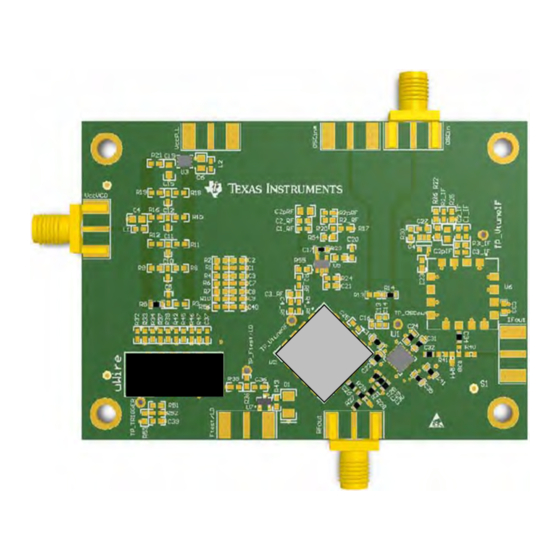
Using the LMX2485E & LMX2487E Evaluation Board
The Texas Instruments LMX2485E-EVM/LMX2487E-EVM helps designers evaluate the operation and
performance of any of the devices in the LMX248x family. Although only two options are offered, the other
members in the family are all pinout compatible and program compatible to one of these existing board
option. They would be expected to have similar performance, just different in the maximum frequency of
operation.
...........................................................................................................................
Topic
..................................................................................................................
1
2
3
4
5
6
Typical Phase Noise Performance Plots
SNAU114D - March 2006 - Revised June 2016
Submit Documentation Feedback
...........................................................................................................
....................................................................................................
...........................................................................................
.......................................................................................................
Copyright © 2006-2016, Texas Instruments Incorporated
SNAU114D - March 2006 - Revised June 2016
................................................................
Using the LMX2485E & LMX2487E Evaluation Board
User's Guide
Page
2
7
8
10
11
13
1
Advertisement

Related Manuals for Texas Instruments LMX2485E-EVM


Summary of Contents for Texas Instruments LMX2485E-EVM
-
Page 1: Table Of Contents
SNAU114D – March 2006 – Revised June 2016 Using the LMX2485E & LMX2487E Evaluation Board The Texas Instruments LMX2485E-EVM/LMX2487E-EVM helps designers evaluate the operation and performance of any of the devices in the LMX248x family. Although only two options are offered, the other members in the family are all pinout compatible and program compatible to one of these existing board option. -
Page 2: Setup
These VCOs were chosen primarily availability, standard footprint, and for lower risk of being obsoleted. WARNING! Due to availability issues, the LMX2485E-EVM has two different suppliers for VCO. Be sure to check the VCO model number to know what VCO model you have! Setup Input/Output Connector Description. - Page 3 VccVCO Connect this to a 5 V Power supply. OSCin Connect this to a signal generator at +4 dBm. Default frequency is 50 MHz for the LMX2485E-EVM and 100 MHz for the LMX2487E-EVM. RFout Connect this to a spectrum analyzer. The board has DC blocking capacitors, so the signal is AC coupled.
- Page 4 Table above . *Remember to also make modifications in “Pin Configuration” Section according to Table above. Using the LMX2485E & LMX2487E Evaluation Board SNAU114D – March 2006 – Revised June 2016 Submit Documentation Feedback Copyright © 2006–2016, Texas Instruments Incorporated...
- Page 5 For detailed design and simulation, please check our PLLatinum Sim Tool. SNAU114D – March 2006 – Revised June 2016 Using the LMX2485E & LMX2487E Evaluation Board Submit Documentation Feedback Copyright © 2006–2016, Texas Instruments Incorporated...
- Page 6 Don’t forget to press <Ctrl>+L or do Keyboard Controls -> Load Device, to load the settings. Using the LMX2485E & LMX2487E Evaluation Board SNAU114D – March 2006 – Revised June 2016 Submit Documentation Feedback Copyright © 2006–2016, Texas Instruments Incorporated...
-
Page 7: Schematic
Schematic Figure 6. LMX2485E/87E-EVM Schematic View Section 3 Bill of Materials for actual component values. SNAU114D – March 2006 – Revised June 2016 Using the LMX2485E & LMX2487E Evaluation Board Submit Documentation Feedback Copyright © 2006–2016, Texas Instruments Incorporated... -
Page 8: Bill Of Materials
Low Noise, RRO Op Amp with Texas Instruments LM6211MF CMOS Input NFET Fairchild BSS138 uWire Header 52601-G10-8LF Using the LMX2485E & LMX2487E Evaluation Board SNAU114D – March 2006 – Revised June 2016 Submit Documentation Feedback Copyright © 2006–2016, Texas Instruments Incorporated... - Page 9 Bill of Materials www.ti.com Table 6. Additional LMX2485E-EVM Specific Components Item Designator Description Manufacturer Part Number LMX2485E Texas Instruments LMX2485E Crystek CVCO55CL-0060-0110 RES, 15k ohm, 5%, 0.1W, 0603 Vishay-Dale CRCW060315K0JNEA RES, 27k ohm, 5%, 0.1W, 0603 Vishay-Dale CRCW060327K0JNEA RES, 0 ohm, 5%, 0.1W, 0603...
-
Page 10: Pcb Layers Stackup
FR4 (Er = 4.8) 23 mil Power Plane #1 23 mil Bottom Layer Figure 7. PCB Layers Using the LMX2485E & LMX2487E Evaluation Board SNAU114D – March 2006 – Revised June 2016 Submit Documentation Feedback Copyright © 2006–2016, Texas Instruments Incorporated... -
Page 11: Pcb Layout
PCB Layout Figure 8. Layer #1 – Top Figure 9. Layer #2 – RF Ground Plane SNAU114D – March 2006 – Revised June 2016 Using the LMX2485E & LMX2487E Evaluation Board Submit Documentation Feedback Copyright © 2006–2016, Texas Instruments Incorporated... - Page 12 PCB Layout www.ti.com Figure 10. Layer #3 – Power Figure 11. Layer #3 – Bottom Layer Using the LMX2485E & LMX2487E Evaluation Board SNAU114D – March 2006 – Revised June 2016 Submit Documentation Feedback Copyright © 2006–2016, Texas Instruments Incorporated...
- Page 13 70.1 MHz, CP Gain = 16x, FM = 2, Dithering Disabled Figure 12. Impact of CPG on Phase Noise SNAU114D – March 2006 – Revised June 2016 Using the LMX2485E & LMX2487E Evaluation Board Submit Documentation Feedback Copyright © 2006–2016, Texas Instruments Incorporated...
- Page 14 70.1 MHz, CP gain = 16x, FM = 4, Dithering Disabled Figure 13. LMX2485E Impact of Fractional Modulator Order Using the LMX2485E & LMX2487E Evaluation Board SNAU114D – March 2006 – Revised June 2016 Submit Documentation Feedback Copyright © 2006–2016, Texas Instruments Incorporated...
- Page 15 70.1 MHz, CP gain = 16x, FM =3, Strong Dithering Figure 14. LMK2485E Impact of Dithering SNAU114D – March 2006 – Revised June 2016 Using the LMX2485E & LMX2487E Evaluation Board Submit Documentation Feedback Copyright © 2006–2016, Texas Instruments Incorporated...
- Page 16 4200.1 MHz, CP gain = 16x, FM = 2, DitheringDisabled Figure 15. LMX2487E Impact of CPG on Phase Noise Using the LMX2485E & LMX2487E Evaluation Board SNAU114D – March 2006 – Revised June 2016 Submit Documentation Feedback Copyright © 2006–2016, Texas Instruments Incorporated...
- Page 17 4200.1 MHz, CP gain = 8x, FM = 4, Dithering Disabled Figure 16. LMX2487E Impact on Fractional Modulator SNAU114D – March 2006 – Revised June 2016 Using the LMX2485E & LMX2487E Evaluation Board Submit Documentation Feedback Copyright © 2006–2016, Texas Instruments Incorporated...
- Page 18 4200.1MHz, CP gain = 8x, FM = 2, Strong Dithering Figure 17. LMX2487E Impact of Dithering Using the LMX2485E & LMX2487E Evaluation Board SNAU114D – March 2006 – Revised June 2016 Submit Documentation Feedback Copyright © 2006–2016, Texas Instruments Incorporated...
- Page 19 Changed BOM Changes from A Revision (July 2013) to B Revision ..................... Page .............. • Added warning that the LMX2485E-EVM has 2 suppliers for VCOs. Changes from Original (December 2009) to A Revision ....................Page .................. • Changed Document was re-created in new format.
- Page 20 STANDARD TERMS AND CONDITIONS FOR EVALUATION MODULES Delivery: TI delivers TI evaluation boards, kits, or modules, including any accompanying demonstration software, components, or documentation (collectively, an “EVM” or “EVMs”) to the User (“User”) in accordance with the terms and conditions set forth herein. Acceptance of the EVM is expressly subject to the following terms and conditions.
- Page 21 FCC Interference Statement for Class B EVM devices NOTE: This equipment has been tested and found to comply with the limits for a Class B digital device, pursuant to part 15 of the FCC Rules. These limits are designed to provide reasonable protection against harmful interference in a residential installation.
- Page 22 【無線電波を送信する製品の開発キットをお使いになる際の注意事項】 開発キットの中には技術基準適合証明を受けて いないものがあります。 技術適合証明を受けていないもののご使用に際しては、電波法遵守のため、以下のいずれかの 措置を取っていただく必要がありますのでご注意ください。 1. 電波法施行規則第6条第1項第1号に基づく平成18年3月28日総務省告示第173号で定められた電波暗室等の試験設備でご使用 いただく。 2. 実験局の免許を取得後ご使用いただく。 3. 技術基準適合証明を取得後ご使用いただく。 なお、本製品は、上記の「ご使用にあたっての注意」を譲渡先、移転先に通知しない限り、譲渡、移転できないものとします。 上記を遵守頂けない場合は、電波法の罰則が適用される可能性があることをご留意ください。 日本テキサス・イ ンスツルメンツ株式会社 東京都新宿区西新宿6丁目24番1号 西新宿三井ビル 3.3.3 Notice for EVMs for Power Line Communication: Please see http://www.tij.co.jp/lsds/ti_ja/general/eStore/notice_02.page 電力線搬送波通信についての開発キットをお使いになる際の注意事項については、次のところをご覧くださ い。http://www.tij.co.jp/lsds/ti_ja/general/eStore/notice_02.page SPACER EVM Use Restrictions and Warnings: 4.1 EVMS ARE NOT FOR USE IN FUNCTIONAL SAFETY AND/OR SAFETY CRITICAL EVALUATIONS, INCLUDING BUT NOT LIMITED TO EVALUATIONS OF LIFE SUPPORT APPLICATIONS.
- Page 23 Notwithstanding the foregoing, any judgment may be enforced in any United States or foreign court, and TI may seek injunctive relief in any United States or foreign court. Mailing Address: Texas Instruments, Post Office Box 655303, Dallas, Texas 75265 Copyright © 2015, Texas Instruments Incorporated...
- Page 24 IMPORTANT NOTICE Texas Instruments Incorporated and its subsidiaries (TI) reserve the right to make corrections, enhancements, improvements and other changes to its semiconductor products and services per JESD46, latest issue, and to discontinue any product or service per JESD48, latest issue.
Need help?
Do you have a question about the LMX2485E-EVM and is the answer not in the manual?
Questions and answers