
Related Manuals for Texas Instruments LMX2594


Summary of Contents for Texas Instruments LMX2594
- Page 1 LMX2594 EVM Instructions – 15-GHz Wideband Low Noise PLL With Integrated VCO User's Guide Literature Number: SNAU210 March 2017...
-
Page 2: Table Of Contents
......................... Trademarks ....................... Evaluation Board Setup ........................EVM Description ....................Installing the Software ..................Bringing LMX2594 to a Lock State ..................Current Loop Filter Configuration ......................Key Results to Expect ........................ Appendix A Schematic ......................Appendix B Bill of Materials .................... -
Page 3: Trademarks
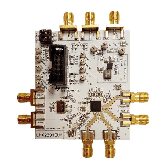
LMX2594 EVM Instructions – 15-GHz Wideband Low Noise PLL With Integrated VCO Figure 1. LMX2594EVM Trademarks SNAU210 – March 2017 LMX2594 EVM Instructions – 15-GHz Wideband Low Noise PLL With Integrated VCO Submit Documentation Feedback Copyright © 2017, Texas Instruments Incorporated... -
Page 4: Evaluation Board Setup
Connect RFoutAM or RFoutAP to a phase noise Analyzer. Connect a 50-Ω on the unused output if you are using only single-ended. Use a balun if you are using differential. LMX2594 EVM Instructions – 15-GHz Wideband Low Noise PLL With SNAU210 – March 2017... -
Page 5: Evm Description
EVM Description www.ti.com EVM Description The LMX2594 is populated on a 4-layer PCB. This brief description should help you use the EVM: Diff. RF Output A Voltage Regulator Not Enabled Power Supply 3.3 Volt Diff. RF Output B LMX2594 Sync... - Page 6 EVM Description www.ti.com The LD switch should be on to enable Lock indicator: Figure 4. LD Lock Detect LMX2594 EVM Instructions – 15-GHz Wideband Low Noise PLL With SNAU210 – March 2017 Integrated VCO Submit Documentation Feedback Copyright © 2017, Texas Instruments Incorporated...
-
Page 7: Installing The Software
2. Install it by following the wizard 3. Search for LMX2594: Click on Select Device From menu bar →PLL+VCO→LMX2594 Figure 5. Search for LMX2594 on TICS Pro 4. You are now ready to use this software. Verify that you can communicate with Reference Pro. Select interface under USB communications: Figure 6. - Page 8 5. Click on identify and you should see the LED (MSP430 Supplied) Blink on Reference Pro Figure 7. USB Communication Between TICS Pro and Reference Pro LMX2594 EVM Instructions – 15-GHz Wideband Low Noise PLL With SNAU210 – March 2017...
-
Page 9: Bringing Lmx2594 To A Lock State
Load the default mode by selecting it as shown in Figure Figure 8. TICS Pro GUI LMX2594 Default Configuration SNAU210 – March 2017 LMX2594 EVM Instructions – 15-GHz Wideband Low Noise PLL With Integrated VCO Submit Documentation Feedback Copyright © 2017, Texas Instruments Incorporated... - Page 10 For best results, in the User Controls Tab in TICS Pro. Under General Controls, check and uncheck the Reset box. After the reset, Write all registers as shown in Figure Figure 9. TICS Pro Write All Registers LMX2594 EVM Instructions – 15-GHz Wideband Low Noise PLL With SNAU210 – March 2017 Integrated VCO Submit Documentation Feedback...
-
Page 11: Current Loop Filter Configuration
For detailed design and simulation, see the PLLatinum Sim Tool. For application notes, blogs,or videos on our products, see http://www.ti.com/pll. SNAU210 – March 2017 LMX2594 EVM Instructions – 15-GHz Wideband Low Noise PLL With Integrated VCO Submit Documentation Feedback Copyright © 2017, Texas Instruments Incorporated... -
Page 12: Key Results To Expect
Figure 11. Phase Noise Plot at 14-GHz Output Frequency This assumes that the input reference is very clean, such as a 100-MHz Wenzel oscillator. A signal generator is NOT sufficiently clean. The LMX2594 requires an external reference. LMX2594 EVM Instructions – 15-GHz Wideband Low Noise PLL With SNAU210 –... -
Page 13: Appendix A Schematic
Appendix A SNAU210 – March 2017 Schematic Figure 12. Schematic SNAU210 – March 2017 Schematic Submit Documentation Feedback Copyright © 2017, Texas Instruments Incorporated... -
Page 14: Appendix B Bill Of Materials
Labels, 0.650" W x 0.200" H - Brady THT-14-423-10 10,000 per roll Switch, SPST, Slide, Off-On, 2 MUXout_SW CTS Electrocomponents 219-2MST Pos, 0.1 A, 20 V, SMD Bill of Materials SNAU210 – March 2017 Submit Documentation Feedback Copyright © 2017, Texas Instruments Incorporated... - Page 15 RES, 51, 5%, 0.1 W, 0603 Vishay-Dale CRCW060351R0JNEA R27, R28 RES, 140, 1%, 0.1 W, 0603 Vishay-Dale CRCW0603140RFKEA Rtps RES, 0, 5%, 0.125 W, 0805 Vishay-Dale CRCW08050000Z0EA SNAU210 – March 2017 Bill of Materials Submit Documentation Feedback Copyright © 2017, Texas Instruments Incorporated...
-
Page 16: Appendix C Board Layers Stack-Up
Appendix C SNAU210 – March 2017 Board Layers Stack-Up Total Board thickness is 62 mils. Figure 13. Board Layer Stack-Up Board Layers Stack-Up SNAU210 – March 2017 Submit Documentation Feedback Copyright © 2017, Texas Instruments Incorporated... -
Page 17: Appendix D Changing Reference Oscillator And Setup
A noise source 10 dB down from the PLL noise will contribute to raise the noise by 0.4 dB. There are different options to provide a reference oscillator to LMX2594: Use on-board oscillator (default), Enable LMK61xx from Reference Pro PCB, use external oscillator. - Page 18 3. Must remove R33 to remove power from oscillator 4. Populate R25 and R30. 5. Remove R32 Figure 15. Differential Reference Configuration Changing Reference Oscillator and Setup SNAU210 – March 2017 Submit Documentation Feedback Copyright © 2017, Texas Instruments Incorporated...
-
Page 19: Appendix E Connecting Reference Pro
Connections from the VDD position to the device supply or from the GND position to the ground plane are connected by 1.5-kΩ resistors. SNAU210 – March 2017 Connecting Reference Pro Submit Documentation Feedback Copyright © 2017, Texas Instruments Incorporated... - Page 20 100-Ω differential termination (R31) is provided on Reference Pro PCB. Removing the differential termination on the EVM is possible if the differential termination is available on the receiver. Connecting Reference Pro SNAU210 – March 2017 Submit Documentation Feedback Copyright © 2017, Texas Instruments Incorporated...
- Page 21 Appendix E www.ti.com Figure 18. LMK61PD0A2 Output Termination SNAU210 – March 2017 Connecting Reference Pro Submit Documentation Feedback Copyright © 2017, Texas Instruments Incorporated...
-
Page 22: Appendix F Ramping Feature
VCO is ramping from 8 to 10 GHz and being dividing by 4 so that it can be seen with the HP53310A. This can be set up on the ramp GUI tab. Figure 19. Ramping Example Tics Ramping Feature SNAU210 – March 2017 Submit Documentation Feedback Copyright © 2017, Texas Instruments Incorporated... - Page 23 Ramping Example Waveform www.ti.com Figure 20. Ramping Example SNAU210 – March 2017 Ramping Feature Submit Documentation Feedback Copyright © 2017, Texas Instruments Incorporated...
-
Page 24: Appendix G Sysref Feature
Appendix G SNAU210 – March 2017 SYSREF Feature Bring LMX2594 to a Lock State 2. Perform Sync Figure 21. Perform Sync For SysRef 3. Configure TICS Pro PLL tab for SysRef • Check the SYSREF_EN box • Change OUTB_MUX to SysRef •... - Page 25 4. Confirm the Interpolator Frequency is between 800 MHz and 1500 MHz • If not, change the SYSREF_DIV_PRE drop-down to Div2 or Div4 to reach an appropriate Interpolator Frequency for the current configuration SNAU210 – March 2017 SYSREF Feature Submit Documentation Feedback Copyright © 2017, Texas Instruments Incorporated...
- Page 26 Figure 23. Interpolator Frequency For SysRef 5. Go to User Controls in the side bar and check the SysRefReq box under the Pins section SYSREF Feature SNAU210 – March 2017 Submit Documentation Feedback Copyright © 2017, Texas Instruments Incorporated...
- Page 27 Appendix G www.ti.com Figure 24. Check SysRefReq Box on User Controls Tab 6. To modify SysRef Frequency, change the value in the SYSREF_DIV box SNAU210 – March 2017 SYSREF Feature Submit Documentation Feedback Copyright © 2017, Texas Instruments Incorporated...
- Page 28 Figure 25. Modifying SysRef Frequency Table 8. SysRef Modes MODE NAME DESCRIPTION TICS PRO - SYS REF SETTINGS Master - LMX2594 generates SysRef pulses as long as SysRefReq pin is held Default mode. See quick start Continuos high. instructions • Uncheck SysRefReq under Pins...
-
Page 29: Appendix H Vco Calibration
HIGH (the low indicates the instant calibration is triggered and running, then high is when done calibration). Adjust the time scale to capture the pulse (approximately 300 µs to start) Figure 26. Unassisted Calibration TICS SNAU210 – March 2017 VCO Calibration Submit Documentation Feedback Copyright © 2017, Texas Instruments Incorporated... - Page 30 Appendix H www.ti.com Figure 27. Unassisted Calibration Plot VCO Calibration SNAU210 – March 2017 Submit Documentation Feedback Copyright © 2017, Texas Instruments Incorporated...
-
Page 31: Appendix I Enabling Onboard Dc-Dc Buck Converter (Tps62150)
4. DC-DC circuitry was optimized for efficiency for 5 to 8 V, but a voltage of 3.3 V to 17 V can be applied to VCC SMA after resistor network is configured correctly from steps above. SNAU210 – March 2017 Enabling Onboard DC-DC Buck Converter (TPS62150) Submit Documentation Feedback Copyright © 2017, Texas Instruments Incorporated... - Page 32 IMPORTANT NOTICE FOR TI DESIGN INFORMATION AND RESOURCES Texas Instruments Incorporated (‘TI”) technical, application or other design advice, services or information, including, but not limited to, reference designs and materials relating to evaluation modules, (collectively, “TI Resources”) are intended to assist designers who are developing applications that incorporate TI products;...
Need help?
Do you have a question about the LMX2594 and is the answer not in the manual?
Questions and answers