Advertisement
Quick Links
LMX2594 EVM Instructions – 15-GHz Wideband Low Noise
This Evaluation Module is for the LMX2594, which is the first PLL with integrated VCO in industry to get
fundamental VCO output up to 15 GHz. The industry leading PLL FOM is –236 dBc/Hz with 1/f of –129
dBc/Hz. This device supports the JESD204B standard (as in the LMX2594 can generate or repeat the
SYSREF signal), and is designed for clock high-speed data converters. The integrated jitter from the EVM
measurements is less than 50 fs at 9-GHz carrier frequency. By providing a SYNC signal, the user can
synchronize the output phase across multiple LMX2594 devices. The LMX2594 can also generate a
frequency ramp as demonstrated in this evaluation module. With an on-board oscillator, the setup process
only requires a 3.3-V power supply and a Reference Pro module (included for SPI Programming
interface). The software is simple with an intuitive and user-friendly GUI.
1
Evaluation Board Setup
2
EVM Description
3
Bringing LMX2594 to a Lock State
4
Loop Filter Configuration
5
Key Results to Expect
SNAU210A – March 2017 – Revised March 2020
Submit Documentation Feedback
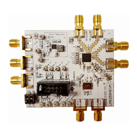
Figure 1. LMX2594EVM
....................................................................................................
.............................................................................................................
........................................................................................
....................................................................................................
.......................................................................................................
LMX2594 EVM Instructions – 15-GHz Wideband Low Noise PLL With
Copyright © 2017–2020, Texas Instruments Incorporated
SNAU210A – March 2017 – Revised March 2020
PLL With Integrated VCO
Contents
User's Guide
3
3
5
5
6
1
Integrated VCO
Advertisement

Related Manuals for Texas Instruments LMX2594EVM


Summary of Contents for Texas Instruments LMX2594EVM
- Page 1 Bringing LMX2594 to a Lock State ....................Loop Filter Configuration ....................... Key Results to Expect SNAU210A – March 2017 – Revised March 2020 LMX2594 EVM Instructions – 15-GHz Wideband Low Noise PLL With Integrated VCO Submit Documentation Feedback Copyright © 2017–2020, Texas Instruments Incorporated...
-
Page 2: Table Of Contents
Appendix H Enabling Onboard DC-DC Buck Converter (TPS62150) Trademarks PLLATINUM is a trademark of Texas Instruments. All other trademarks are the property of their respective owners. LMX2594 EVM Instructions – 15-GHz Wideband Low Noise PLL With SNAU210A – March 2017 – Revised March 2020... - Page 3 Connect USB cable from laptop or PC to USB port in Reference Pro. This provides power to Reference Pro board and communication with TICS GUI. b. Connect 10 pin ribbon cable from Reference Pro to LMX2594EVM as shown above. 4. Output: a.
- Page 4 5. Click on Identify and you will see the LED (MSP430 Supplied) blinks on Reference Pro. LMX2594 EVM Instructions – 15-GHz Wideband Low Noise PLL With SNAU210A – March 2017 – Revised March 2020 Integrated VCO Submit Documentation Feedback Copyright © 2017–2020, Texas Instruments Incorporated...
- Page 5 C1_LF 390 pF C2_LF 68 nF C3_LF Open C4_LF 1800 pF SNAU210A – March 2017 – Revised March 2020 LMX2594 EVM Instructions – 15-GHz Wideband Low Noise PLL With Integrated VCO Submit Documentation Feedback Copyright © 2017–2020, Texas Instruments Incorporated...
- Page 6 This assumes that the input reference is very clean, such as a 100-MHz Wenzel oscillator. A signal generator is NOT sufficiently clean. LMX2594 EVM Instructions – 15-GHz Wideband Low Noise PLL With SNAU210A – March 2017 – Revised March 2020 Integrated VCO Submit Documentation Feedback Copyright © 2017–2020, Texas Instruments Incorporated...
-
Page 7: Appendix A Schematic
Appendix A SNAU210A – March 2017 – Revised March 2020 Schematic Figure 10. Schematic SNAU210A – March 2017 – Revised March 2020 Schematic Submit Documentation Feedback Copyright © 2017–2020, Texas Instruments Incorporated... -
Page 8: Appendix B Bill Of Materials
JACK, SMA, 50 Ω, Gold, Edge Mount Johnson 142-0771-831 Wideband RF Synthesizer Texas Instruments LMX2594RHAR Header (shrouded), 100 mil, 5x2, Gold uWire 52601-S10-8LF plated, SMD Bill of Materials SNAU210A – March 2017 – Revised March 2020 Submit Documentation Feedback Copyright © 2017–2020, Texas Instruments Incorporated... -
Page 9: Appendix C Board Layers Stack-Up
FR4 (Er = 4.6) Power layer FR4 (Er = 4.6) Bottom layer Figure 11. Board Layer Stack-Up Figure 12. Top Layer SNAU210A – March 2017 – Revised March 2020 Board Layers Stack-Up Submit Documentation Feedback Copyright © 2017–2020, Texas Instruments Incorporated... - Page 10 Appendix C www.ti.com Figure 13. GND Layer Figure 14. Power Layer Figure 15. Bottom Layer Board Layers Stack-Up SNAU210A – March 2017 – Revised March 2020 Submit Documentation Feedback Copyright © 2017–2020, Texas Instruments Incorporated...
-
Page 11: Appendix D Changing Reference Oscillator And Setup
Table 5. Reference Clock Input Configuration INPUT EXTERNAL CLOCK CRYSTAL OSCILLATOR Single- ended Differential (LVDS) SNAU210A – March 2017 – Revised March 2020 Changing Reference Oscillator and Setup Submit Documentation Feedback Copyright © 2017–2020, Texas Instruments Incorporated... -
Page 12: Appendix E Connecting Reference Pro
To use Reference Pro, change the configuration for SE or differential connection as shown on Appendix Figure 16. LMX2594EVM Setup With Reference Pro The LMK61PD0A2 has several control pins dedicated for output format control, output frequency control, and output enable control. These control pins can be configured through the jumpers shown in... - Page 13 100-Ω differential termination (R31) is provided on Reference Pro PCB. Removing the differential termination on the EVM is possible if the differential termination is available on the receiver. Figure 17. LMK61PD0A2 Output Termination SNAU210A – March 2017 – Revised March 2020 Connecting Reference Pro Submit Documentation Feedback Copyright © 2017–2020, Texas Instruments Incorporated...
-
Page 14: Appendix F Ramping Feature
VCO is ramping from 12 to 12.125 GHz. This can be set up on the ramp GUI tab. Figure 18. Ramping Example Figure 19. Ramping Example Ramping Feature SNAU210A – March 2017 – Revised March 2020 Submit Documentation Feedback Copyright © 2017–2020, Texas Instruments Incorporated... -
Page 15: Appendix Gsysref Feature
RFOUTB will repeat external input to SysRefReq pin. • Uncheck SysRefReq Repeater Output will be reclocked to LMX2594 internal • Check SysRef_Repeat frequency SNAU210A – March 2017 – Revised March 2020 SYSREF Feature Submit Documentation Feedback Copyright © 2017–2020, Texas Instruments Incorporated... -
Page 16: Appendix H Enabling Onboard Dc-Dc Buck Converter (Tps62150)
4. DC-DC circuitry was optimized for efficiency for 5 to 8 V, but a voltage of 3.3 V to 17 V can be applied to VCC SMA after resistor network is configured correctly from steps above. Enabling Onboard DC-DC Buck Converter (TPS62150) SNAU210A – March 2017 – Revised March 2020 Submit Documentation Feedback Copyright © 2017–2020, Texas Instruments Incorporated... - Page 17 Changed to use external reference clock......................• Added PCB layout diagrams..............• Added diagrams for different reference clock input configuration. SNAU210A – March 2017 – Revised March 2020 Revision History Submit Documentation Feedback Copyright © 2017–2020, Texas Instruments Incorporated...
- Page 18 STANDARD TERMS FOR EVALUATION MODULES Delivery: TI delivers TI evaluation boards, kits, or modules, including any accompanying demonstration software, components, and/or documentation which may be provided together or separately (collectively, an “EVM” or “EVMs”) to the User (“User”) in accordance with the terms set forth herein.
- Page 19 www.ti.com Regulatory Notices: 3.1 United States 3.1.1 Notice applicable to EVMs not FCC-Approved: FCC NOTICE: This kit is designed to allow product developers to evaluate electronic components, circuitry, or software associated with the kit to determine whether to incorporate such items in a finished product and software developers to write software applications for use with the end product.
- Page 20 www.ti.com Concernant les EVMs avec antennes détachables Conformément à la réglementation d'Industrie Canada, le présent émetteur radio peut fonctionner avec une antenne d'un type et d'un gain maximal (ou inférieur) approuvé pour l'émetteur par Industrie Canada. Dans le but de réduire les risques de brouillage radioélectrique à...
- Page 21 www.ti.com EVM Use Restrictions and Warnings: 4.1 EVMS ARE NOT FOR USE IN FUNCTIONAL SAFETY AND/OR SAFETY CRITICAL EVALUATIONS, INCLUDING BUT NOT LIMITED TO EVALUATIONS OF LIFE SUPPORT APPLICATIONS. 4.2 User must read and apply the user guide and other available documentation provided by TI regarding the EVM prior to handling or using the EVM, including without limitation any warning or restriction notices.
- Page 22 Notwithstanding the foregoing, any judgment may be enforced in any United States or foreign court, and TI may seek injunctive relief in any United States or foreign court. Mailing Address: Texas Instruments, Post Office Box 655303, Dallas, Texas 75265 Copyright © 2019, Texas Instruments Incorporated...
- Page 23 TI products. TI’s provision of these resources does not expand or otherwise alter TI’s applicable warranties or warranty disclaimers for TI products. Mailing Address: Texas Instruments, Post Office Box 655303, Dallas, Texas 75265 Copyright © 2020, Texas Instruments Incorporated...
- Page 24 Mouser Electronics Authorized Distributor Click to View Pricing, Inventory, Delivery & Lifecycle Information: Texas Instruments LMX2594EVM...
Need help?
Do you have a question about the LMX2594EVM and is the answer not in the manual?
Questions and answers