Table of Contents
Advertisement
Quick Links
LMX2595 EVM Instructions – 20-GHz Wideband Low Noise
This Evaluation Module is for the LMX2595, which is the first PLL with integrated VCO in industry to get
fundamental VCO output up to 20 GHz. The industry leading PLL FOM is –236 dBc/Hz with 1/f of –129
dBc/Hz. This device supports the JESD204B standard (as in the LMX2595 can generate or repeat the
SYSREF signal), and is designed for clock high-speed data converters. The integrated jitter from the EVM
measurements is less than 50 fs at 9-GHz carrier frequency. By providing a SYNC signal, the user can
synchronize the output phase across multiple LMX2595 devices. The LMX2595 can also generate a
frequency ramp as demonstrated in this evaluation module. With an on-board oscillator, the setup process
only requires a 3.3-V power supply and an included Reference Pro module (For SPI Programming
interface). The software is simple with an intuitive and user-friendly GUI.
1
Evaluation Board Setup
2
EVM Description
2.1
Installing the Software
3
Bringing LMX2595 to a Lock State
4
Loop Filter Configuration
SNAU219B – June 2017 – Revised March 2020
Submit Documentation Feedback
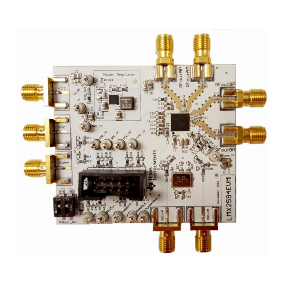
Figure 1. LMX2595EVM
....................................................................................................
.............................................................................................................
..............................................................................................
........................................................................................
....................................................................................................
LMX2595 EVM Instructions – 20-GHz Wideband Low Noise PLL With
Copyright © 2017–2020, Texas Instruments Incorporated
SNAU219B – June 2017 – Revised March 2020
PLL With Integrated VCO
Contents
User's Guide
3
3
4
5
5
1
Integrated VCO
Advertisement
Table of Contents

Related Manuals for Texas Instruments LMX2595 EVM


Summary of Contents for Texas Instruments LMX2595 EVM
- Page 1 ..................Bringing LMX2595 to a Lock State ....................Loop Filter Configuration SNAU219B – June 2017 – Revised March 2020 LMX2595 EVM Instructions – 20-GHz Wideband Low Noise PLL With Integrated VCO Submit Documentation Feedback Copyright © 2017–2020, Texas Instruments Incorporated...
-
Page 2: Table Of Contents
Trademarks PLLATINUM is a trademark of Texas Instruments. All other trademarks are the property of their respective owners. LMX2595 EVM Instructions – 20-GHz Wideband Low Noise PLL With SNAU219B – June 2017 – Revised March 2020 Integrated VCO Submit Documentation Feedback... - Page 3 Lock Reference input indicator SE or Diff Figure 3. LMX2595EVM Description SNAU219B – June 2017 – Revised March 2020 LMX2595 EVM Instructions – 20-GHz Wideband Low Noise PLL With Integrated VCO Submit Documentation Feedback Copyright © 2017–2020, Texas Instruments Incorporated...
- Page 4 Figure 5. USB Communications on TICS Pro 5. Click on Identify and you will see the LED (MSP430 Supplied) blinks on Reference Pro. LMX2595 EVM Instructions – 20-GHz Wideband Low Noise PLL With SNAU219B – June 2017 – Revised March 2020...
- Page 5 C1_LF 390 pF C2_LF 68 nF C3_LF Open C4_LF 1800 pF SNAU219B – June 2017 – Revised March 2020 LMX2595 EVM Instructions – 20-GHz Wideband Low Noise PLL With Integrated VCO Submit Documentation Feedback Copyright © 2017–2020, Texas Instruments Incorporated...
-
Page 6: Key Results To Expect
This assumes that the input reference is very clean, such as a 100-MHz Wenzel oscillator. A signal generator is NOT sufficiently clean. LMX2595 EVM Instructions – 20-GHz Wideband Low Noise PLL With SNAU219B – June 2017 – Revised March 2020... -
Page 7: Appendix A Schematic
Appendix A SNAU219B – June 2017 – Revised March 2020 Schematic Figure 10. Schematic SNAU219B – June 2017 – Revised March 2020 Schematic Submit Documentation Feedback Copyright © 2017–2020, Texas Instruments Incorporated... -
Page 8: Appendix B Bill Of Materials
142-0771-831 High Performance, Wideband PLLatinum™ Texas Instruments LMX2595RHAR RF Synthesizer Header (shrouded), 100 mil, 5x2, Gold uWire 52601-S10-8LF plated, SMD Bill of Materials SNAU219B – June 2017 – Revised March 2020 Submit Documentation Feedback Copyright © 2017–2020, Texas Instruments Incorporated... -
Page 9: Appendix C Board Layers Stack-Up
FR4 (Er = 4.6) Power layer FR4 (Er = 4.6) Bottom layer Figure 11. Board Layer Stack-Up Figure 12. Top Layer SNAU219B – June 2017 – Revised March 2020 Board Layers Stack-Up Submit Documentation Feedback Copyright © 2017–2020, Texas Instruments Incorporated... - Page 10 Appendix C www.ti.com Figure 13. GND Layer Figure 14. Power Layer Figure 15. Bottom Layer Board Layers Stack-Up SNAU219B – June 2017 – Revised March 2020 Submit Documentation Feedback Copyright © 2017–2020, Texas Instruments Incorporated...
-
Page 11: Appendix D Changing Reference Oscillator And Setup
Table 5. Reference Clock Input Configuration INPUT EXTERNAL CLOCK CRYSTAL OSCILLATOR Single- ended Differential (LVDS) SNAU219B – June 2017 – Revised March 2020 Changing Reference Oscillator and Setup Submit Documentation Feedback Copyright © 2017–2020, Texas Instruments Incorporated... -
Page 12: Appendix E Connecting Reference Pro
1.5-kΩ resistors. Table 6. Output Frequency of LMK61PD0A2 (Reference Pro) OUTPUT FREQUENCY (MHz) 312.5 106.25 156.25 212.5 62.5 Connecting Reference Pro SNAU219B – June 2017 – Revised March 2020 Submit Documentation Feedback Copyright © 2017–2020, Texas Instruments Incorporated... - Page 13 100-Ω differential termination (R31) is provided on Reference Pro PCB. Removing the differential termination on the EVM is possible if the differential termination is available on the receiver. Figure 17. LMK61PD0A2 Output Termination SNAU219B – June 2017 – Revised March 2020 Connecting Reference Pro Submit Documentation Feedback Copyright © 2017–2020, Texas Instruments Incorporated...
-
Page 14: Appendix F Ramping Feature
VCO is ramping from 12 to 12.125 GHz. This can be set up on the ramp GUI tab. Figure 18. Ramping Example Figure 19. Ramping Example Ramping Feature SNAU219B – June 2017 – Revised March 2020 Submit Documentation Feedback Copyright © 2017–2020, Texas Instruments Incorporated... -
Page 15: Appendix Gsysref Feature
RFOUTB will repeat external input to SysRefReq pin. • Uncheck SysRefReq Repeater Output will be reclocked to LMX2595 internal • Check SysRef_Repeat frequency SNAU219B – June 2017 – Revised March 2020 SYSREF Feature Submit Documentation Feedback Copyright © 2017–2020, Texas Instruments Incorporated... -
Page 16: Appendix H Enabling Onboard Dc-Dc Buck Converter (Tps62150)
4. DC-DC circuitry was optimized for efficiency for 5 to 8 V, but a voltage of 3.3 V to 17 V can be applied to VCC SMA after resistor network is configured correctly from steps above. Enabling Onboard DC-DC Buck Converter (TPS62150) SNAU219B – June 2017 – Revised March 2020 Submit Documentation Feedback Copyright © 2017–2020, Texas Instruments Incorporated... -
Page 17: Appendix I Appendix J: Using The Vco Doubler
Figure 22. VCO Frequency Doubler Setup in TICSPro Figure 23. 18 GHz Phase Noise Using VCO Doubler SNAU219B – June 2017 – Revised March 2020 Appendix J: Using the VCO Doubler Submit Documentation Feedback Copyright © 2017–2020, Texas Instruments Incorporated... - Page 18 Changes from A Revision (July 2019) to B Revision ..................... Page ..................• Changed VCO output from: 19 GHz to: 20 GHz Revision History SNAU219B – June 2017 – Revised March 2020 Submit Documentation Feedback Copyright © 2017–2020, Texas Instruments Incorporated...
- Page 19 Changed to use external reference clock......................• Added PCB layout diagrams..............• Added diagrams for different reference clock input configuration. SNAU219B – June 2017 – Revised March 2020 Revision History Submit Documentation Feedback Copyright © 2017–2020, Texas Instruments Incorporated...
- Page 20 TI products. TI’s provision of these resources does not expand or otherwise alter TI’s applicable warranties or warranty disclaimers for TI products. TI objects to and rejects any additional or different terms you may have proposed. IMPORTANT NOTICE Mailing Address: Texas Instruments, Post Office Box 655303, Dallas, Texas 75265 Copyright © 2022, Texas Instruments Incorporated...
Need help?
Do you have a question about the LMX2595 EVM and is the answer not in the manual?
Questions and answers