Table of Contents
Advertisement
Quick Links
www.ti.com
User's Guide
LMX2820EVM Evaluation Module
Noel Fung
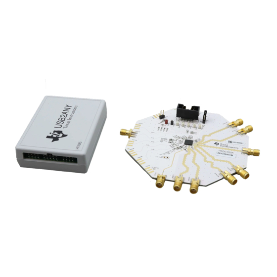
The LMX2820EVM is designed to evaluate the performance of LMX2820. This board consists of a LMX2820
device.
The LMX2820 is a high-performance wideband synthesizer that can generate any frequency from 44.14 MHz to
22.6 GHz. The device runs from a single 3.3-V supply and has integrated LDOs that eliminate the need for
onboard low noise LDOs.
1
Trademarks..............................................................................................................................................................................2
2 LMX2820EVM Evaluation
2.1 Evaluation Module Contents..............................................................................................................................................
2.2 Evaluation Setup Requirement..........................................................................................................................................
2.3 Resources..........................................................................................................................................................................
SNAU246A – JUNE 2020 – REVISED JANUARY 2021
Submit Document Feedback
ABSTRACT
Table of Contents
Module..........................................................................................................................................3
Copyright © 2021 Texas Instruments Incorporated
Table of Contents
LMX2820EVM Evaluation Module
3
3
3
1
Advertisement
Table of Contents

Subscribe to Our Youtube Channel
Related Manuals for Texas Instruments LMX2820EVM


Summary of Contents for Texas Instruments LMX2820EVM
- Page 1 LMX2820EVM Evaluation Module Noel Fung ABSTRACT The LMX2820EVM is designed to evaluate the performance of LMX2820. This board consists of a LMX2820 device. The LMX2820 is a high-performance wideband synthesizer that can generate any frequency from 44.14 MHz to 22.6 GHz. The device runs from a single 3.3-V supply and has integrated LDOs that eliminate the need for onboard low noise LDOs.
-
Page 2: Table Of Contents
Figure 4-4. Offset Mixing With PFDIN Pin Setting........................Figure 4-5. External VCO Mode Setting............................Figure 4-6. Register Readback..............................9 Figure 5-1. LMX2820EVM Schematic (Page 1).........................10 Figure 5-2. LMX2820EVM Schematic (Page 2)......................... Figure 6-1. PCB Layer Stack-Up............................... Figure 6-2. Top Layer.................................12 Figure 6-3. RF GND Layer.................................13 Figure 6-4. - Page 3 A PC running Windows 7 or more recent version • An oscilloscope (optional) • A high quality signal generator (optional) • Texas Instruments Clocks and Synthesizers TICS Pro software • Texas Instruments PLLatinum ™ Simulator Tool (optional) 2.3 Resources Related evaluation and development resources are as follows: •...
-
Page 4: Setup
3.5 Programming Connect the ribbon cable from the USB2ANY to the LMX2820EVM. Connect the USB cable from a PC to USB port in the USB2ANY. This provides power supply to the USB2ANY and communication with the TICS Pro. A firmware update may be required. See Appendix B for more details. -
Page 5: Evaluation Software
2. The "ReadMe" page will load. Please take a minute to read the content to have a basic understanding of the GUI. 3. Go to Default Configuration → EVM Default Mode. Figure 3-3. Default Mode SNAU246A – JUNE 2020 – REVISED JANUARY 2021 LMX2820EVM Evaluation Module Submit Document Feedback Copyright © 2021 Texas Instruments Incorporated... -
Page 6: Typical Measurement
VALUE C1_LF 470 pF C2_LF 68 nF C3_LF 2.2 nF R2_LF 68.1 Ω R3_LF 18.2 Ω Figure 4-1. Loop Filter LMX2820EVM Evaluation Module SNAU246A – JUNE 2020 – REVISED JANUARY 2021 Submit Document Feedback Copyright © 2021 Texas Instruments Incorporated... -
Page 7: Figure 4-2. Default Output
2. Click Write All Registers to write all the registers to LMX2820. The default output is 6 GHz. Figure 4-2. Default Output SNAU246A – JUNE 2020 – REVISED JANUARY 2021 LMX2820EVM Evaluation Module Submit Document Feedback Copyright © 2021 Texas Instruments Incorporated... -
Page 8: Additional Tests
CPG. Figure 4-4. Offset Mixing With PFDIN Pin Setting LMX2820EVM Evaluation Module SNAU246A – JUNE 2020 – REVISED JANUARY 2021 Submit Document Feedback Copyright © 2021 Texas Instruments Incorporated... -
Page 9: Figure 4-5. External Vco Mode Setting
In addition to the internal VCO, LMX2820 also support working with an external VCO. The polarity of the phase detector has to be set properly to match with the actual Vtune characteristic. The LMX2820EVM offers various options to implement passive or active loop filter onboard. -
Page 10: Schematic
Schematic www.ti.com 5 Schematic Figure 5-1. LMX2820EVM Schematic (Page 1) LMX2820EVM Evaluation Module SNAU246A – JUNE 2020 – REVISED JANUARY 2021 Submit Document Feedback Copyright © 2021 Texas Instruments Incorporated... -
Page 11: Figure 5-2. Lmx2820Evm Schematic
Schematic Figure 5-2. LMX2820EVM Schematic (Page 2) SNAU246A – JUNE 2020 – REVISED JANUARY 2021 LMX2820EVM Evaluation Module Submit Document Feedback Copyright © 2021 Texas Instruments Incorporated... -
Page 12: Pcb Layout And Layer Stack-Up
Signal GND layer FR4 (Er = 4.2) Bottom layer Figure 6-1. PCB Layer Stack-Up 6.2 PCB Layout Figure 6-2. Top Layer LMX2820EVM Evaluation Module SNAU246A – JUNE 2020 – REVISED JANUARY 2021 Submit Document Feedback Copyright © 2021 Texas Instruments Incorporated... -
Page 13: Figure 6-3. Rf Gnd Layer
PCB Layout and Layer Stack-Up Figure 6-3. RF GND Layer Figure 6-4. Signal GND Layer SNAU246A – JUNE 2020 – REVISED JANUARY 2021 LMX2820EVM Evaluation Module Submit Document Feedback Copyright © 2021 Texas Instruments Incorporated... -
Page 14: Figure 6-5. Bottom Layer
PCB Layout and Layer Stack-Up www.ti.com Figure 6-5. Bottom Layer LMX2820EVM Evaluation Module SNAU246A – JUNE 2020 – REVISED JANUARY 2021 Submit Document Feedback Copyright © 2021 Texas Instruments Incorporated... -
Page 15: Bill Of Materials
Test Point, Miniature, Black, TH 5001 Keystone TP12 Test Point, Miniature, Red, TH 5000 Keystone RF Synthesizer LMX2820 Texas Instruments SNAU246A – JUNE 2020 – REVISED JANUARY 2021 LMX2820EVM Evaluation Module Submit Document Feedback Copyright © 2021 Texas Instruments Incorporated... -
Page 16: Troubleshooting Guide
• Register read back requires the correct software setup. See Section 4.2.4 for details. • The POR current of the LMX2820EVM is approximately 220 mA. • The power-down current of the LMX2820EVM is approximately 10 mA. Start Congratulation! Device locked Verify hardware setup: Validate power supply is connected, turned on, and current limit is appropriate for the device. -
Page 17: A Using Different Reference Clock
Using Different Reference Clock A Using Different Reference Clock These are the different options to provide a reference clock to LMX2820EVM. By default, the EVM is configured for an external single-ended clock. Table A-1. Reference Clock Input Configuration DIFFERENTIAL CLOCK SINGLE-ENDED CLOCK SNAU246A –... -
Page 18: B Usb2Any Firmware Upgrade
Usually when the USB2ANY module is used the first time, TICS Pro will request a firmware update. Follow the pop-up instructions to complete the update. This is necessary to ensure that the USB connection between the PC and the USB2ANY module is properly set up, otherwise the programming to LMX2820EVM will not be successful. -
Page 19: Figure B-4. Update Firmware
5. Click Upgrade Firmware to start the firmware upgrade. Click Close after the upgrade is complete. Figure B-5. Firmware Update Complete SNAU246A – JUNE 2020 – REVISED JANUARY 2021 LMX2820EVM Evaluation Module Submit Document Feedback Copyright © 2021 Texas Instruments Incorporated... -
Page 20: C Revision History
Updated graphic and changed external PFD mode to offset mixing with PFDIN pin in the Offset Mixing With PFDIN Pin section.............................. • Updated graphic in External VCO Mode section....................LMX2820EVM Evaluation Module SNAU246A – JUNE 2020 – REVISED JANUARY 2021 Submit Document Feedback Copyright © 2021 Texas Instruments Incorporated... - Page 21 STANDARD TERMS FOR EVALUATION MODULES Delivery: TI delivers TI evaluation boards, kits, or modules, including any accompanying demonstration software, components, and/or documentation which may be provided together or separately (collectively, an “EVM” or “EVMs”) to the User (“User”) in accordance with the terms set forth herein.
- Page 22 www.ti.com Regulatory Notices: 3.1 United States 3.1.1 Notice applicable to EVMs not FCC-Approved: FCC NOTICE: This kit is designed to allow product developers to evaluate electronic components, circuitry, or software associated with the kit to determine whether to incorporate such items in a finished product and software developers to write software applications for use with the end product.
- Page 23 www.ti.com Concernant les EVMs avec antennes détachables Conformément à la réglementation d'Industrie Canada, le présent émetteur radio peut fonctionner avec une antenne d'un type et d'un gain maximal (ou inférieur) approuvé pour l'émetteur par Industrie Canada. Dans le but de réduire les risques de brouillage radioélectrique à...
- Page 24 www.ti.com EVM Use Restrictions and Warnings: 4.1 EVMS ARE NOT FOR USE IN FUNCTIONAL SAFETY AND/OR SAFETY CRITICAL EVALUATIONS, INCLUDING BUT NOT LIMITED TO EVALUATIONS OF LIFE SUPPORT APPLICATIONS. 4.2 User must read and apply the user guide and other available documentation provided by TI regarding the EVM prior to handling or using the EVM, including without limitation any warning or restriction notices.
- Page 25 Notwithstanding the foregoing, any judgment may be enforced in any United States or foreign court, and TI may seek injunctive relief in any United States or foreign court. Mailing Address: Texas Instruments, Post Office Box 655303, Dallas, Texas 75265 Copyright © 2019, Texas Instruments Incorporated...
- Page 26 TI products. TI’s provision of these resources does not expand or otherwise alter TI’s applicable warranties or warranty disclaimers for TI products.IMPORTANT NOTICE Mailing Address: Texas Instruments, Post Office Box 655303, Dallas, Texas 75265 Copyright © 2021, Texas Instruments Incorporated...
Need help?
Do you have a question about the LMX2820EVM and is the answer not in the manual?
Questions and answers