
Subscribe to Our Youtube Channel
Related Manuals for BEA ORASCAN P


Summary of Contents for BEA ORASCAN P
- Page 1 ORASCAN P Opening & Safety sensor for automatic sliding doors (according to EN 16005 and DIN 18650 including emergency exits). User's Guide for software version 0100 and higher (refer to tracking label on product)
-
Page 2: Intended Use
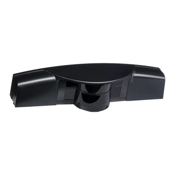
INTENDED USE The ORASCAN is an opening and safety sensor for sliding doors using dual technology: Artek radar technology for smart opening and time-of-flight laser for a complete 180° safety coverage of the door threshold, including side screen safety. A module must be installed on both sides of the door. -
Page 3: Installation Tips
1. TIPS INSTALLATION TIPS Avoid vibrations. Do not cover the laser Avoid moving objects Avoid presence of window. and light sources in smoke in the the detection field. detection field Avoid condensation. Avoid exposure to Keep the sensor sudden and extreme permanently powered temperature changes. -
Page 4: Led Signals
2. DESCRIPTION Cover Mounting base Bluetooth® LED (white) Red push button Radar antenna BLUESPIN connectors White push button (+) BLUESPIN LED (white) Power cable Black push button (-) Main LED (multi color) BLUESPIN cable DIP-switch Sidescreen safety : right side (red) Connectors Sidescreen safety : left side (red) LED SIGNALS... - Page 5 3. MOUNTING ON DOOR NOTE The ORASCAN sensor must be paired with another ORASCAN using the supplied BLUESPIN cable. ORASCANS can be connected to a door controller using previously installed IXIO cables. Please refer to the application note. Remove the cover: Insert a screwdriver on the left or the right notch of the sensor and twist it.
- Page 6 Remove the positioning aids from the base. Fasten the 2 screws using a Torx screwdriver. The base needs to be fixed firmly and securely! Drill through the 2 bases and the door using a 14mm bit in order to pass the POWER and the BLUESPIN cables.
- Page 7 4. WIRING Power supply: 12-30VDC Opening: Main Orascan Safety: Door threshold Opening: Current source Safety: Door sidescreen Opening: Secondary Orascan CAUTION External electrical sources must ensure double insulation from primary voltages.
- Page 8 1 Electronic relays galvanic isolation (polarity free) • Max. contact current : 100 mA • Max. contact voltage: 42V DC / 30V AC • in switching mode: NO/NC • in frequency mode: pulsed signal in no detection (f = 100 Hz ) •...
-
Page 9: Dip Switch Settings
5. DIP SWITCH SETTINGS DIP 1 : MOUNTING SIDE ON : INSIDE OFF : OUTSIDE* DIP 2 : ESCAPE ROUTE ON : RADAR OUTPUT > FREQUENCY + CURRENT OFF : RADAR OUTPUT > NO* Switch to ON to ESCAPE ROUTE to use the radar output in frequency or current source mode for an emergency exit application. -
Page 10: Service Mode
After changing a DIP- switch, the main LED blinks orange. A long push on the red push button confirms the settings. SERVICE MODE The service mode deactivates the safety detection during 15 minutes and can be useful during an installation, a mechanical teach-in of the door or maintenance work. -
Page 11: Field Size
FIELD SIZE Use the white button to increase the field size and the black button to decrease the field size. SHAPE Wide mode: press the black button 3s, when the LED turns purple, press the white one. Narrow mode: press the black button 3s, when the LED turns purple, press the black one. - Page 12 7. TEACH-IN NOTE - Make sure the door operates in summer mode (full opening) during the teach-in. - Make sure you and anyone else are outside the detection field during the teach-in process. If people are inside the detection field, the sensor may not work as expected. - If the moving panels have no metallic frame, activate the "fog &...
- Page 13 All you need to do is press the red square push button and wait outside of the laser curtains. LED starts flashing red-green. The door opens automatically. You can hear the motor positioning the curtains correctly. The sensor learns its environment, defines the safety areas and then does a few opening and closing cycles.
- Page 14 Press the black square push button to move the laser curtains towards the back of the door. Press the white square push button to move the laser curtains towards the front of the door. Press square push button. starts blinking red-green. The door opens automatically.
-
Page 15: Troubleshooting
Once paired, the Bluetooth® LED is ON. The Bluetooth® word mark and logos are registered trademarks owned by Bluetooth SIG, Inc. and any use of such marks by BEA sa is underlicense. Other trademarks and trade names are those of their respective owners 9. TROUBLESHOOTING... - Page 16 Status Explanation / Solution The ORANGE LED Communication error between modules blinks 3x Check that the DIP1 of both Orascan are set to different mounting sides of the door. Check wiring between the sensors on the BLUESPIN bus. Press the red push button during 3 seconds if a sensor (e.g Eagle Artek) has been permanently removed from the BLUESPIN bus (note: not applicable to both modules of an ORASCAN kit) The ORANGE LED...
- Page 17 Status Explanation / Solution Red LED lights The sensor vibrates. up sporadically or Check if the sensor is fastened firmly. permanently. Check position of cable and cover. The sensor sees the door or door frame. Launch a new teach-in. Unwanted detections (due to environment or external conditions). Clear field Verify if the laser window is dirty and clean it with compressed air.
-
Page 18: Technical Specifications
10. TECHNICAL SPECIFICATIONS Supply voltage 12 – 30V DC +/-10% External electrical sources must ensure double insulation from primary voltages. Max Power <5W consumption Mounting Height 2m to 3,5m Temperature range -25°C to +55°C; 0-95% relative humidity, non condensing Vibrations <2G Degree of protection IP54 (IEC/EN 60529) - Page 19 Conformity BEA hereby declares that this product is in compliance with European legislation 2006/42/EC (Machinery), 2014/53/EU (RED) and 2011/65/EU (RoHS). The complete declaration of conformity is available on our website. EC-type examination certificate from TÜV NORD CERT: 44 205 13089646...
- Page 20 WWW.BEASENSORS.COM BEA SA | LIEGE Science Park | ALLÉE DES NOISETIERS 5 - 4031 ANGLEUR [BELGIUM] | T +32 4 361 65 65 | F +32 4 361 28 58 | info-eu@beasensors.com| WWW.BEASENSORS.COM Manufactured by: BEA SA - LIEGE Science Park - Allée des Noisetiers 5 - 4031 Angleur - Belgium - T +32 4 3616565 - F +32 4 3612858 - info-eu@beasensors.com - www.beasensors.com...
Need help?
Do you have a question about the ORASCAN P and is the answer not in the manual?
Questions and answers