Table of Contents
Advertisement
Quick Links
Advertisement
Table of Contents

Subscribe to Our Youtube Channel
Related Manuals for THORLABS LSK-GR08


Summary of Contents for THORLABS LSK-GR08
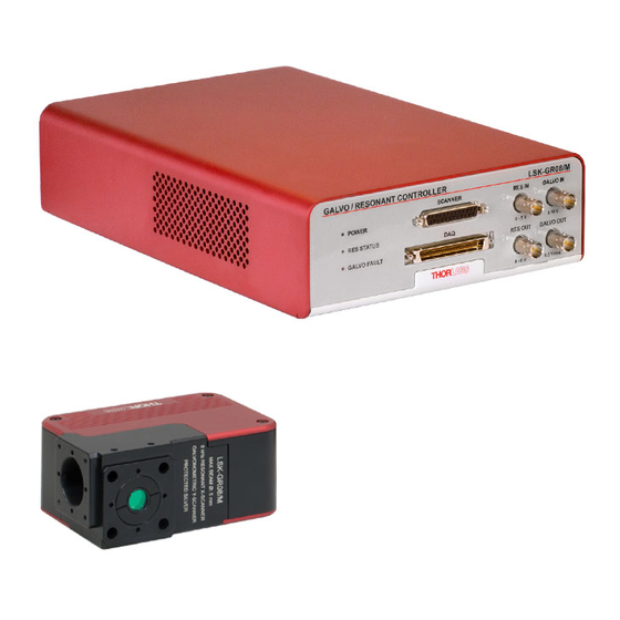
- Page 1 LSK-GR08(/M) 8 kHz Galvo-Resonant Scanner and Controller User Guide...
- Page 2 8 kHz Galvo-Resonant Scanner and Controller Copyright May 20, 2019 Thorlabs, Inc. All rights reserved. Information in this document is subject to change without notice. The software described in this document is furnished under a license agreement or nondisclosure agreement. The software may be used or copied only in accordance with the terms of those agreements.
-
Page 3: Table Of Contents
3.1. Overview ............... 3 3.2. Connector Choices............3 Chapter 4 Getting Started ..............5 4.1. Unpacking and Inspection ..........5 4.2. Setting Up the LSK-GR08(/M) ......... 5 4.2.1. Preparation .................. 5 Chapter 5 Software ................7 5.1. LSK-GR Software Development Kit (SDK) Installation ..7 5.2. - Page 4 7.7. NIR Window ..............27 Chapter 8 NI PCIe 6321 Card Schematic ........28 Chapter 9 Mechanical Drawings ............. 29 Chapter 10 Certifications and Compliance........32 Chapter 11 Warranty ................33 Chapter 12 Regulatory ............... 34 Chapter 13 Thorlabs Worldwide Contacts........35...
-
Page 5: Chapter 1 Warning Symbol Definitions
8 kHz Galvo-Resonant Scanner and Controller Chapter 1: Warning Symbol Definitions Chapter 1 Warning Symbol Definitions Below is a list of warning symbols you may encounter in this manual or on your device. Symbol Description Direct Current Alternating Current Both Direct and Alternating Current Earth Ground Terminal Protective Conductor Terminal Frame or Chassis Terminal... -
Page 6: Chapter 2 Safety
WARNING DO NOT use the device for anything other than its intended use. If the device is used in a manner not specified by Thorlabs, the protection provided by the equipment may be impaired. CAUTION DO NOT operate in a wet, damp, or explosive environment. -
Page 7: Chapter 3 Description
SM05 (0.535"-40) threads. The output face has internal SM1 threads and four 4-40 tapped holes for our 30 mm cage system. Thorlabs’ Cage Plate Adapter can be used to convert these ports to a 60 mm cage system that is capable of holding a scan lens. - Page 8 8 kHz Galvo-Resonant Scanner and Controller Chapter 3: Description BNC Control and Power and Monitor Signal Lines Fault LEDs NI 68-Pin Connector DB-25 Connector Figure 1 Galvo-Resonant Controller Front Panel Power Fuse Holder Power Input Switch USB Port Ground Connector Figure 2 Galvo-Resonant Controller Back Panel Page 4 TTN118194-D02...
-
Page 9: Chapter 4 Getting Started
AC Power Cord Galvo-Resonant Scanner Software CD Inspect the package contents for any missing parts or damage. If there is a problem, please contact our nearest office (see Chapter 13: Thorlabs Worldwide Contacts for details). 4.2. Setting Up the LSK-GR08(/M) - Page 10 Connect the other end of the BNC cable to any DC voltage generator (0 - 5 V). Connect one end of the AC power cord to the LSK-GR08(/M) and the other end to a standard power outlet. Turn on the power switch located on the back panel of the controller.
-
Page 11: Chapter 5 Software
The resonant scan angle can be controlled via LSK-GR software. 5.1. LSK-GR Software Development Kit (SDK) Installation Insert the LSK-GR08 Software CD into the computer, and open 70-0058 - LSK-GR SDK folder. Double click the Installer (.exe) application to open the LSKGR Setup window. - Page 12 8 kHz Galvo-Resonant Scanner and Controller Chapter 5: Software In the Choose Components window, select SDK if you want the software development kit files installed, then click Next. Figure 5 Choose Components Window In the Choose Install Location window, select the destination folder you like the files installed, then click Install.
- Page 13 8 kHz Galvo-Resonant Scanner and Controller Chapter 5: Software The LSKGR setup will begin installation. Figure 7 Installing Window During installation, the Device Driver Installation Wizard window will appear. Click Next to begin installing the software drivers that some computer devices need in order to work. Figure 8 Device Driver Installation Wizard Window Rev B, May 20, 2019 Page 9...
- Page 14 8 kHz Galvo-Resonant Scanner and Controller Chapter 5: Software Once drivers are installed, click Finish to complete drivers installation. Figure 9 Completing the Device Driver Installation Wizard Window 10. The installer will automatically search your computer for Microsoft Visual C++ 2012 Redistributable (x64) – 11.0.61030 and Microsoft .NET 4.5.2. It will download and install them if they are not found on your computer.
- Page 15 8 kHz Galvo-Resonant Scanner and Controller Chapter 5: Software 11. Once done installing the necessary software, select Reboot now and click Finish in the Completing Thorlabs LSKGR Setup window to close Setup window and restart your computer. Figure 11 Completing Thorlabs LSKGR 4.0 Setup Window 12.
-
Page 16: Com Port Number Configuration
COM Port Number Configuration Check Device Manager>Port (COM & LPT) on your computer to verify the COM port of Thorlabs LSK-GR08 Galvo Res Scanner driver. Make sure the COM Port Number is set to COM48. To change the COM Port Number to COM48:... - Page 17 Click OK on the LSK-GR08 Galvo Res Scanner Properties window. Unplug and reinsert the USB cable into the computer. Note: The COM Port Number for LSK-GR08 Galvo Res Scanner must appear as COM48 on the Device Manager. Rev B, May 20, 2019...
-
Page 18: Gui (Graphical User Interface)
8 kHz Galvo-Resonant Scanner and Controller Chapter 5: Software 5.3. GUI (Graphical User Interface) The GUI consists of the menu and the display area. Menu Display Area Figure 16 LSK-GR Control Window 5.3.1. GUI Display Area The display area shows the serial number, firmware version, field size, and alignment controls. -
Page 19: Gui Menu
Click File>Update Firmware to open the file path for the .hex file (provided by Thorlabs). Select the .hex file, and click Open to update the firmware. See Section 5.4: Updating the Firmware if you are updating the firmware for the first time. -
Page 20: Updating The Firmware
5.4. Updating the Firmware Make sure to update your firmware immediately if you receive a newer version of LSK-GR firmware from Thorlabs. Save the latest firmware (.hex file) on your computer. Open the LSK-GR Control window, and click File>Update Firmware. - Page 21 Figure 23 Firmware Update Finished Window Check the device manager. LSK-GR08 Galvo Res Scanner should appear as a new device in the Device Manager. Make sure the COM Port Number is set to COM48. To change the COM Port Number, see Section 5.2: COM Port Number Configuration...
-
Page 22: Chapter 6 Maintaining The Lsk-Gr08(/M)
Chapter 6: Maintaining the LSK-GR08(/M) Chapter 6 Maintaining the LSK-GR08(/M) There are no serviceable parts in the LSK-GR08(/M). If you suspect a problem with the LSK-GR08(/M), please contact our nearest office for assistance from an applications engineer (see Chapter 13: Thorlabs Worldwide Contacts for details). -
Page 23: Troubleshooting
8 kHz Galvo-Resonant Scanner and Controller Chapter 6: Maintaining the LSK-GR08(/M) 6.2. Troubleshooting Problem Solution RES STATUS and/or GALVO Check all cable connections. FAULT LED turns on. Make sure the Scan Head is free from any obstruction. ... -
Page 24: Replacing The Fuse
Check to see if the fuse is blown. If you see a black/brown smudge on the fuse glass, a clearly broken wire, or no wire at all, the fuse is blown. If the fuse is good, contact Thorlabs Technical Support for further assistance. - Page 25 8 kHz Galvo-Resonant Scanner and Controller Chapter 6: Maintaining the LSK-GR08(/M) Replace the blown fuse and insert the fuse holder into the Controller. Figure 27 Properly Installed Fuse Rev B, May 20, 2019 Page 21...
-
Page 26: Chapter 7 Specifications
8 kHz Galvo-Resonant Scanner and Controller Chapter 7: Specifications Chapter 7 Specifications 7.1. General Specifications Specification Value 4.60" x 3.45" x 2.00" Scan Head Dimensions (116.8 mm x 87.7 mm x 50.8 mm) Galvo/Resonant Controller 12.30" x 7.87" x 3.12" Dimensions (312.4 mm x 199.8 mm x 79.2 mm) Galvo Control Voltage... -
Page 27: Scan Head Performance Specifications
8 kHz Galvo-Resonant Scanner and Controller Chapter 7: Specifications 7.2. Scan Head Performance Specifications Specification Value Natural Resonant Frequency 7910 Hz Frequency Tolerance -15 to 15 Hz Sync Signal Frequency 8 kHz Sync Signal Pulse Width 50% Duty Cycle Maximum Beam Diameter 5 mm Maximum Scan Range for a Square 10°... -
Page 28: Galvo Mirror Specifications
8 kHz Galvo-Resonant Scanner and Controller Chapter 7: Specifications 7.3. Galvo Mirror Specifications Specification Value Mirror Substrate Silicon Coating Protected Silver 350 - 450 nm >70% 450 - 550 nm >90% Coating Reflectivity 550 - 650 nm >92.5% 650 - 1080 nm >95% 1080 - 7000 nm >97%... -
Page 29: Resonant Mirror Specifications
8 kHz Galvo-Resonant Scanner and Controller Chapter 7: Specifications 7.4. Resonant Mirror Specifications Specification Value Mirror Substrate Optical Grade Beryllium Coating Protected Silver 350 - 450 nm >70% 450 - 550 nm >90% Coating Reflectivity 550 - 650 nm >92.5% 650 - 1080 nm >95% 1080 - 7000 nm... -
Page 30: Choosing A Scanner Lens
8 kHz Galvo-Resonant Scanner and Controller Chapter 7: Specifications 7.6. Choosing a Scanner Lens Figure 28 Mirror Distance Specifications Input Distance = Distance from the input face to the first mirror (Blue Line) + 0.5 x Distance between the two mirrors (Green Line) 25.09 + 0.5 x 7.13 = 28.655 mm Output Distance = Distance from the second mirror to the output face (Yellow Line) + 0.5 x Distance between the two mirrors (Green Line) -
Page 31: Nir Window
8 kHz Galvo-Resonant Scanner and Controller Chapter 7: Specifications 7.7. NIR Window Figure 29 Typical NIR Window Reflectance Figure 30 NIR Window Substrate Material Transmission Rev B, May 20, 2019 Page 27... -
Page 32: Chapter 8 Ni Pcie 6321 Card Schematic
8 kHz Galvo-Resonant Scanner and Controller Chapter 8: NI PCIe 6321 Card Schematic Chapter 8 NI PCIe 6321 Card Schematic Figure 31 NI PCIe 6321 Pinout Signal Name Description Characteristics 100 kΩ Input Galvo Position IN Position In Signal Impedance 1 kΩ... -
Page 33: Chapter 9 Mechanical Drawings
8 kHz Galvo-Resonant Scanner and Controller Chapter 9: Mechanical Drawings Chapter 9 Mechanical Drawings Figure 32 Mechanical Drawing of LSK-GR08 Scan Head Rev B, May 20, 2019 Page 29... - Page 34 8 kHz Galvo-Resonant Scanner and Controller Chapter 9: Mechanical Drawings Figure 33 Mechanical Drawing of LSK-GR08/M Scan Head Page 30 TTN118194-D02...
- Page 35 8 kHz Galvo-Resonant Scanner and Controller Chapter 9: Mechanical Drawings Figure 34 Mechanical Drawing of LSK-GR08(/M) Controller Rev B, May 20, 2019 Page 31...
-
Page 36: Chapter 10 Certifications And Compliance
8 kHz Galvo-Resonant Scanner and Controller Chapter 10: Certifications and Compliance Chapter 10 Certifications and Compliance Page 32 TTN118194-D02... -
Page 37: Chapter 11 Warranty
8 kHz Galvo-Resonant Scanner and Controller Chapter 11: Warranty Chapter 11 Warranty Thorlabs warrants that all products sold by Thorlabs will conform to the published specifications and shall be free from defects in material and workmanship under normal use, handling, and service. -
Page 38: Chapter 12 Regulatory
Waste Treatment is Your Own Responsibility If you do not return an “end of life” unit to Thorlabs, you must hand it to a company specialized in waste recovery. Do not dispose of the unit in a litter bin or at a public waste disposal site. -
Page 39: Chapter 13 Thorlabs Worldwide Contacts
8 kHz Galvo-Resonant Scanner and Controller Chapter 13: Thorlabs Worldwide Contacts Chapter 13 Thorlabs Worldwide Contacts For technical support or sales inquiries, please visit us at www.thorlabs.com/contact for our most up-to-date contact information. USA, Canada, and South America UK and Ireland Thorlabs, Inc. Thorlabs Ltd. - Page 40 www.thorlabs.com...
Need help?
Do you have a question about the LSK-GR08 and is the answer not in the manual?
Questions and answers