Table of Contents
Advertisement
Quick Links
Advertisement
Table of Contents

Related Manuals for THORLABS MDT693B


Summary of Contents for THORLABS MDT693B
- Page 1 MDT693B and MDT694B Open-Loop Piezo Controllers User Guide...
-
Page 2: Table Of Contents
5.4. MDT694B Rear Panel Overview..................... 6 5.5. Setting the Output Voltage Limit ....................7 5.6. Using INT Adjustment Knob ......................7 5.7. Using EXT Input BNC ........................8 5.8. Master Scan Control (MDT693B Only) ..................8 ....................10 Chapter 6 Bandwidth Performance 6.1. -
Page 3: Chapter 1 Warning Symbol Definitions
Open-Loop Piezo Controllers Chapter 1: Warning Symbol Definitions Warning Symbol Definitions Chapter 1 Below is a list of warning symbols you may encounter in this manual or on your device. Symbol Description Direct Current Alternating Current Both Direct and Alternating Current Earth Ground Terminal Protective Conductor Terminal Frame or Chassis Terminal... -
Page 4: Chapter 2 Safety
Besides storing charge from the MDT693B or MDT694B, the piezo can accumulate static charge over time due to varying storage temperature and/or mechanical loads. To safely discharge a piezo, connect it to the MDT693B or MDT694B and set the output voltage to 0 volts. -
Page 5: Chapter 3 Description
0 - 100 V (Gain = 10 V/V) or 0 - 150 V (Gain = 15 V/V) operation. The Master Scan feature on the MDT693B allows all three channels to be controlled by one manual adjuster or one external control signal. -
Page 6: Chapter 4 Setup
3. Carefully use a flat blade screwdriver to open the fuse tray. 4. Remove the existing fuse and install the appropriate fuse (600 mA for the MDT693B, 500 mA for the MDT694B). The replacement fuse must be a 5 mm x 20 mm, 250 VAC Type T Fuse (IEC 60127-2/III, low breaking capacity, slow blow). -
Page 7: Chapter 5 Operation
Open-Loop Piezo Controllers Chapter 5: Operation Operation Chapter 5 5.1. MDT693B Front Panel Overview Master INT Master EX T Input 7-Segment LED EXT Input Master Voltage Modulation Input 4 Digits Modulation Input Adjust 0 – 10 V 0 – 10 V... -
Page 8: Mdt694B Front Panel Overview
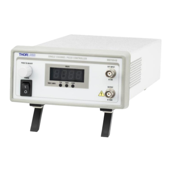
Open-Loop Piezo Controllers Chapter 5: Operation 5.3. MDT694B Front Panel Overview 7-Segment LED 4 Digits EXT Input Modulation Input 0 – 10 V INT Control Knob Voltage Adjustment Power Switch Turns Unit HV Output On and Off 1 Channel Output CAUTION: High Voltage 5.4. -
Page 9: Setting The Output Voltage Limit
Follow the procedure described on the next page for operation in this mode. 1. Attach a piezo to one of the high voltage output connectors on the rear panel of the MDT693B or the front panel of the MDT694B. -
Page 10: Using Ext Input Bnc
10 V. To use this feature, follow the steps below. 1. Attach a piezo to one of the high voltage output connectors on the rear panel of the MDT693B or the front panel of the MDT694B. - Page 11 Open-Loop Piezo Controllers Chapter 5: Operation input is only active when Master Scan mode is active (i.e., the enable LED must be lit). Note that the individual EXT in for each channel is disabled when Master Scan mode is active. Master Scan INT The MASTER SCAN INT knob allows adjustment of all three channels over the full operating range of 0 V to 75 V, 0 V to 100 V, or 0 V to 150 V.
-
Page 12: Chapter 6 Bandwidth Performance
Since the piezo can be modeled most accurately as a capacitor, the piezo will create a low-pass filter with the output impedance of the driver. For both the MDT693B and MDT694B, the output impedance is specified as 150 , 1 nF. - Page 13 Open-Loop Piezo Controllers Chapter 6: Bandwidth Performance Linear Ramp Signal ∆�� �� = �� ( ������ ∆�� ��(∆��) ∆�� = ( �� ������ Triangle Wave ∆�� �� = 2�� ( ������ ∆�� ��(∆��) ∆�� = ( �� ������ �� = ∆��...
-
Page 14: Chapter 7 Remote Communications
MDT693B or MDT694B. From the dialog box that is displayed, select the Install Drivers button. Follow the onscreen prompts to install the driver. After the driver is installed, attach the MDT693B or MDT694B to the PC and power it on. Your PC will then detect the new hardware and will prompt you when the installation is complete. -
Page 15: Keywords (Commands And Queries)
Open-Loop Piezo Controllers Chapter 7: Remote Communications 7.3. Keywords (Commands and Queries) The following list shows all available commands and queries, and summarizes their functions for the MDT693B: Command Syntax Description Get Commands List the available commands. Product Information Returns the product header and firmware version... - Page 16 Open-Loop Piezo Controllers Chapter 7: Remote Communications The following list shows all available commands and queries, and summarizes their functions for the MDT694B: Command Syntax Description Get Commands List the available commands. Product Information Returns the product header and firmware version Restore Default Settings restore Restores default factory settings...
-
Page 17: Chapter 8 Specifications
USB 2.0 The MDT693B and MDT694B were tested without an external load connected (1 nF output impedance only). Adding a capacitive load, such as a piezo, will decrease the noise spec since the capacitance will create a low-pass filter with the output resistance. - Page 18 Power On Rocker Switch Scan Trim Controls 4-Turn Potentiometer Remote Interface USB Type B Physical Specifications Parameter MDT693B MDT694B Display Type 7-Segment LED with 4 Digits Display Resolution 0.1 V Number of Displays Number of Channels 12.18" x 4.15" x 8.55"...
-
Page 19: Chapter 9 Mechanical Drawings
Open-Loop Piezo Controllers Chapter 9: Mechanical Drawings Mechanical Drawings Chapter 9 9.1. MDT693B Mechanical Drawing 9.2. MDT694B Mechanical Drawing Rev F, April 12, 2023 Page 17... -
Page 20: Chapter 10 Troubleshooting
100 to 240 VAC. 2. Fuse(s) may be open. Refer to Section 4.2 for information on replacing open fuses. If the problem persists, please return the unit to Thorlabs for evaluation. I cannot adjust the voltage. -
Page 21: Chapter 11 Warranty
Thorlabs, Inc. warrants the material and production of the MDT69xB Piezo Controller for a period of 24 months from the date of shipment. During this warranty period, Thorlabs, Inc. will repair or exchange any units found to be defective in material or workmanship. -
Page 22: Chapter 12 Regulatory
12.1. Waste Treatment is Your Own Responsibility If you do not return an “end of life” unit to Thorlabs, you must hand it to a company specialized in waste recovery. Do not dispose of the unit in a litter bin or at a public waste disposal site. -
Page 23: Chapter 13 Certifications And Compliance
Open-Loop Piezo Controllers Chapter 13: Certifications and Compliance Chapter 13 Certifications and Compliance Rev F, April 12, 2023 Page 21... - Page 24 Open-Loop Piezo Controllers Chapter 13: Certifications and Compliance Page 22 TTN011225-D02...
-
Page 25: Chapter 14 Thorlabs Worldwide Contacts
Open-Loop Piezo Controllers Chapter 14: Thorlabs Worldwide Contacts Chapter 14 Thorlabs Worldwide Contacts For technical support or sales inquiries, please visit us at www.thorlabs.com/contact for our most up-to-date contact information. USA, Canada, and South America UK and Ireland Thorlabs, Inc. - Page 26 www.thorlabs.com...
Need help?
Do you have a question about the MDT693B and is the answer not in the manual?
Questions and answers