Table of Contents
Advertisement
Quick Links
Advertisement
Table of Contents

Subscribe to Our Youtube Channel
Related Manuals for True Fitness RR1-0A-35


Summary of Contents for True Fitness RR1-0A-35
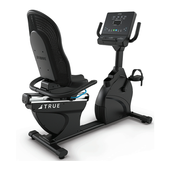
- Page 1 RESIDENTIAL RECUMBENT BIKE OWNER’S MODEL RR1-0A-35 MANUAL MAN-RR1-0A-35 REV00...
-
Page 2: Important-Please Read
IMPORTANT—PLEASE READ All products shown are prototype. Actual product delivered may vary. Product specifi cations, features, and software are subject to change without notice. For the most up-to-date version of this manual, please see our website: https://shop.truefi tness.com/customer-service/user-manuals/ CONTACTING OUR SUPPORT TEAM To contact TRUE for any of your pre or post installation questions, please call our toll-free numbers Monday - Friday 8:30am - 5:00pm (CST): •... -
Page 3: Reporting Freight Claims Or Parts Damage
REPORTING FREIGHT CLAIMS OR PARTS DAMAGE Unfortunately, sometimes materials can be damaged during shipment. If materials are damaged during shipment, please follow the guidelines below to determine the appropriate process for you to follow. Severe Damage—Obvious damage to external packaging and internal product. Please refuse the shipment and it will be returned to TRUE by the carrier. -
Page 4: Table Of Contents
TABLE OF CONTENTS SAFETY INSTRUCTIONS IMPORTANT SAFETY INSTRUCTIONS—SAVE THESE INSTRUCTIONS............5 POWER REQUIREMENTS..........................7 GROUNDING INSTRUCTIONS........................7 SPACE REQUIREMENTS...........................8 SPECIFICATIONS..........................8 WARNING DECALS...........................9 COMPLIANCES...........................9 PROPER USE............................10 ASSEMBLY INSTRUCTIONS PREASSEMBLY CHECKLIST........................11 ASSEMBLY STEPS..........................14 PRODUCT FEATURES BASE OVERVIEW............................28 CONSOLE OVERVIEW..........................29 CARE AND MAINTENANCE INSPECTION..........................30 CLEANING THE EQUIPMENT........................30 LEVELING THE EQUIPMENT........................30 PREVENTATIVE MAINTENANCE......................31 LONG TERM STORAGE..........................31... -
Page 5: Safety Instructions
SAFETY INSTRUCTIONS IMPORTANT SAFETY INSTRUCTIONS—SAVE THESE INSTRUCTIONS This equipment intended for in-home use only. Do not use this product in any commercial, rental, school or institutional setting. • Read and understand all instructions and warnings prior to use. • Obtain a medical exam before beginning any exercise program. If at any time during exercise you feel faint, dizzy, or experience pain, stop and consult your physician. - Page 6 • Use a TRUE AC power cord or AC/DC adapter only. • Wear shoes with rubber or high traction soles. Do not use shoes with heels, leather soles, cleats or spikes. • Position this product so the power cord plug is Make sure no stones are embedded in the soles.
-
Page 7: Power Requirements
(usually on the front of the unit). Depending on where you live voltage requirements grounded differ. outlet grounding pin Power Information Line Rated Number of Max Power Frequency Model Voltage Current Units per Plug/Outlet Dissipation (Hz) (Amps) Circuit (Watt) NEMA 5-15 RR1-0A-35 50/60Hz 1230... -
Page 8: Space Requirements
SPACE REQUIREMENTS TRUE recommends leaving a minimum of 24” (61cm) on each side of the equipment and a 79” (200cm) safety zone at the rear of the equipment. 24” (61cm) 24” 79” (61cm) (200cm) 24” (61cm) SPECIFICATIONS • DIMENSIONS (L X W X H) 58”... -
Page 9: Warning Decals
WARNING DECALS WARNING: Replace warning labels that may be worn, damaged, or missing. To replace any worn or missing decals contact TRUE product support (service@truefi tness.com | 800.883.8783). console serial number location base serial number location COMPLIANCES This equipment complies with all applicable codes and regulations. For a complete list of compliances, please visit www.truefi... -
Page 10: Proper Use
PROPER USE Proper Training Position • Once seated, users should place their feet on the pedals (A). • When pedaling, the user should be able to extend their legs fully while pedaling; if users do not have enough room to fully extend their legs, they should adjust their seat position (B) until their legs are able to comfortably extend. -
Page 11: Assembly Instructions
ASSEMBLY INSTRUCTIONS NOTE: Supplemental video available @TRUEFitnessservicevids. PREASSEMBLY CHECKLIST BASIC GUIDELINES FOR SETTING UP THE EQUIPMENT After removing the equipment from the packaging, place the equipment on a clean, level surface. Make sure the electrical cord easily reaches a grounded three-pronged outlet. DANGER: Do not use an extension cord or ungrounded outlet. -
Page 12: Box Contents
BOX CONTENTS ITEM DESCRIPTION Base Seat Handlebar Seat Back Cover Seat Back Bottom Console Cover Front Mast Rear Console Cover Left Pedal Right Pedal Rear Stabilizer Front Stabilizer Rear Pivot Cover Hardware Bag(s) Manual Chest Strap Power Adapter *The 9V, 1.3A power adapter is for LED consoles only. Touchscreen consoles require a 12V, 3A power adapter, which is included with touchscreen consoles. - Page 13 HARDWARE BAG CONTENTS Step 5—Seat Back Hardware Step 12—Console Covers Hardware ITEM DESCRIPTION ITEM DESCRIPTION SHCS, M6 X 16MM, LOCK PATCH PHMS, M4-0.7 X 10MM, PHILLIPS TCS4029 PS8054 LOCK WASHER, M6-1.0 Tools FE0130 ITEM DESCRIPTION 5MM ALLEN WRENCH WASHER, FLAT 6.5 X 13 X 1.0T BLK FE0094 Step 6—Rear Pivot Cover Hardware ITEM...
-
Page 14: Assembly Steps
ASSEMBLY STEPS Step 1—Attach Rear Stabilizer Parts Used in this Step Tools Used in this Step Item Part Description 8mm Allen Wrench RB0002-35 REAR STABILIZER ASSEMBLY RCS0368 SHCS, M10-1.5 X 55MM FE0090 WASHER, SPRING, M10 RCS0369 WASHER, FLAT, 10MM X 20MM, T=2MM A. - Page 15 Step 2—Attach Front Stabilizer Parts Used in this Step Tools Used in this Step Item Part Description 8mm Allen Wrench RB0001-35 FRONT STABILIZER ASSEMBLY RCS0368 SHCS, M10-1.5 X 55MM FE0090 WASHER, SPRING, M10 RCS0369 WASHER, FLAT, 10MM X 20MM, T=2MM A.
- Page 16 Step 3—Connect Seat Handlebar Cables After making sure the handlebar is in the correct position, connect the thumbswitch cables and contact heart rate cables. NOTE: At least one person should hold the handlebar in place while the other makes the cable connections. Thumbswitch Thumbswitch Cable...
- Page 17 Step 4—Attach Seat Handlebar Tools Used in this Step Parts Used in this Step Item Part Description 5mm Allen Wrench RB0128-35 SEAT HANDLEBAR ASSEMBLY CM8-125-20FH BOLT FHCS M8x1.25_20 BZ FE0179 SHCS, M8-1.25 X 20MM 6mm Allen Wrench PS0099 SPRING WASHER, M8 CM8-19FW FLAT WASHER, 8MM X 19MM X 2MM A.
- Page 18 Step 5—Attach Seat Back Parts Used in this Step Tools Used in this Step Item Part Description 5mm Allen Wrench RB0117 SEAT BACK ASSEMBLY PS8054 SHCS, M6 X 16MM, LOCK PATCH FE0130 LOCK WASHER, M6-1.0 FE0094 WASHER, FLAT 6.5 X 13 X 1.0T BLK Using a 5mm allen wrench, install the seat back onto the seat carriage using eight socket head cap screws, spring washers, and fl...
- Page 19 Step 6—Attach Rear Pivot Cover Parts Used in this Step Tools Used in this Step Item Part Description #2 Phillips Screwdriver RCS0036RBK REAR PIVOT COVER FE0187 BHCS, M5-0.85 X 15MM RCS0382 WASHER, FLAT, 5.5MM X 15MM, T=1MM A. Attach the rear pivot cover onto the seat carriage. NOTE: The rear pivot cover should attach cleanly to the front pivot cover.
- Page 20 Step 7—Attach Seat Back Cover Parts Used in this Step Tools Used in this Step Item Part Description #2 Phillips Screwdriver RB0136BK SEAT BACK COVER TC0056 BHCS, M5-0.85 X 20MM Using a #2 Phillips screwdriver, attach the seat back cover to the seat back using four screws.
- Page 21 Step 8—Attach Pedals Parts Used in this Step Tools Used in this Step Item Part Description 15mm Wrench RB0076BKL PEDAL ASSEMBLY LEFT RB0076BKR PEDAL ASSEMBLY RIGHT Torque Wrench With 15mm Head A. Using a 15mm wrench, attach each pedal to its corresponding crank. B.
- Page 22 Step 9—Route Cables Up Front Mast Parts Used in this Step Item Part Description RCS0014-35 FRONT MAST ASSEMBLY RCS0031BK BOTTOM CONSOLE PLASTIC RB0062BK BOTTLE HOLDER A. Remove the storage dock from the base. C. Pull the cables coming from the front of the bike through the front mast using the provided pull tie.
- Page 23 Step 10—Attach Front Mast Parts Used in this Step Tools Used in this Step Item Part Description 6mm Allen Wrench RCS0014-35 FRONT MAST ASSEMBLY SX0124 BHCS, M10-1.5 X 20MM, BLK ZP FE0090 WASHER, SPRING, M10 RCS0369 WASHER, FLAT, 10MM X 20MM, T=2MM A.
- Page 24 Step 11—Attach Console to Front Mast Tools Used in this Step #2 Phillips Screwdriver A. If the console has three screws (00567700 // SCREW, M4-.7 X 12 PPHMS SEMS) preassembled, remove and set aside these screws. They are not used in the installation. Remove and set aside the four screws (00567800 // SCREW, M5-.8X12 COMBO PHILLIPS/COMMON TRUSS HEAD - ACG BLACK) preassembled to the console.
- Page 25 Step 12—Attach Console Covers Tools Used in this Step Parts Used in this Step Item Part Description #2 Phillips Screwdriver RCS0022BK REAR CONSOLE COVER RCS0031BK BOTTOM CONSOLE PLASTIC TCS4029 PHMS, M4-0.7 X 10MM, PHILLIPS A. Using a #2 Phillips screwdriver, attach the rear console cover to the front mast using two screws. B.
- Page 26 Step 13—Level the Machine Tools Used in this Step 19mm Wrench A. Verify the bike is resting on the fl oor and not on any packaging materials. B. Using a 19mm wrench, adjust all four leveling feet until they contact the fl oor. IMPORTANT! DO NOT adjust the leveling feet to such a height that they detach or unscrew from the machine.
- Page 27 Step 14—Connect the Power Adapter A. Make the correct power connections for the base and console: • If the console is a touchscreen use the 12V, 3A power adapter. • If the console is an LED use the 9V, 1.3A power adapter. B.
-
Page 28: Product Features
PRODUCT FEATURES BASE OVERVIEW Console Assembly Seat Contact Heart Rate Grip Quick Access Pedals Control Power Inlet Leveling Feet Console Assembly—The console allows the user to set up a Leveling Feet—An adjustable system used to level the workout program and control the machine during a workout. machine. -
Page 29: Console Overview
CONSOLE OVERVIEW Touchscreen Console LED Console 8 8 8 8 8 8 8 8 8 8 8 8 8 8 8 8 8 8 8 8 8 8 8 8 8 8 8 8 8 8 8 8 8 8 8 8 8 8 8 8 8 8 8 8 8... -
Page 30: Care And Maintenance
CARE AND MAINTENANCE It is important to perform the minor maintenance tasks described in this section. Failure to maintain the bike as described here could void the TRUE Warranty. To reduce the risk of electrical shock, always unplug the unit from its power source before cleaning or performing any maintenance tasks. -
Page 31: Preventative Maintenance
SCHEDULING QUARTERLY PREVENTATIVE MAINTENANCE TRUE recommends scheduling quarterly preventative maintenance with a qualifi ed service provider. Please contact your dealer or visit www.truefi tness.com to contact a local TRUE authorized service provider. QUARTERLY PREVENTATIVE MAINTENANCE • Record time, distance, and hours from the console. •... -
Page 32: Additional Information
ADDITIONAL INFORMATION TROUBLESHOOTING This troubleshooting information is intended to assist in diagnostics only and is not all inclusive. Technical specifi cations, error codes, and programming are subject to change without notice. TRUE accepts no liability for any damage or loss suffered by persons whom rely wholly or in part on any description or statement contained within this manual. -
Page 33: Limited Warranty
Coax/TV, HDMI, USB, mirroring or Ethernet Wear Items*** 180 Days connections, and safety key. All TRUE Fitness products are distributed by TRUE and are • The remedies described herein are your sole and warranted to the original registered product purchaser exclusive remedies and TRUE’... -
Page 34: Warranty Registration
WARRANTY REGISTRATION Thank you for purchasing a TRUE product! PLEASE RETAIN THIS PORTION FOR YOUR RECORDS To validate your product warranty, you must register BASE SERIAL NUMBER: your product within 30 days of purchaser’ s receipt of this CONSOLE SERIAL NUMBER: product. - Page 36 1.800.883.8783 865 Hoff Road St. Louis, MO 63366 T R U E F I T N E S S . C O M MAN-RR1-0A-35 Owner’s Manual, Assembly Guide, and Warranty Card REV00 © 2024 TRUE Fitness All Rights Reserved...
Need help?
Do you have a question about the RR1-0A-35 and is the answer not in the manual?
Questions and answers