
Subscribe to Our Youtube Channel
Related Manuals for True Fitness SD1000


Summary of Contents for True Fitness SD1000
- Page 1 *Assembly Guide & Warranty Card Included LEG EXTENSION/LEG CURL OWNER’S MANUAL Model # SD1000 Revision 031717...
- Page 2 FORCE STRENGTH OWNERS MANUAL IMPORTANT: All Products shown are prototype. Actual product delivered may vary. Product specifications, features & software are subject to change without notice. For the most up to date owner’s manual please visit www.truefitness.com. For documents in additional languages please visit www.truefitness.com/resources/document-library/ IMPORTANTE: Todos los productos mostrados son prototipos.
- Page 3 FORCE STRENGTH OWNERS MANUAL Frank Trulaske began TRUE Fitness over thirty-five year ago with the simple philosophy of delivering superior fitness products, service and support. Today, TRUE is the global leader in premium fitness equipment for the commercial and residential markets. Our goal is to be the leader in technology, innovation, performance, safety and style.
-
Page 4: Table Of Contents
FORCE STRENGTH OWNERS MANUAL TABLE OF CONTENTS: Chapter 1: Safety Instructions Chapter 5: Customer Service Safety Instructions Contacting Service Space Requirements Contacting Sales Working Dimensions Reporting Freight Claims or Parts Damage Warning Decals Chapter 6: Additional Information Proper Training Position Specification Sheet Chapter 2: Assembly Instructions Warranty Registration... -
Page 5: Chapter 1: Safety Instructions
*for additional information visit http://oehha.ca.gov/prop65 WARNING: Keep equipment stable on flat ground. True Fitness recommends for all strength equipment to be bolted down to the floor to avoid toppling during improper use. WARNING: Replace warning labels that may be worn, damaged or missing. - Page 6 CHAPTER 1: SAFETY INSTRUCTIONS CAUTION: • Health related injuries may result from incorrect or excessive use of exercise equipment. • Take care when getting on or off strength equipment. • If you do not understand how to use/operate a piece of equipment seek assistance from facility staff or trainer to demonstrate safe and proper use.
-
Page 7: Space Requirements
CHAPTER 1: SAFETY INSTRUCTIONS SPACE REQUIREMENTS: TRUE’s recommendation is to leave a 40” (1.0m) safety zone on all sides of the unit. Additionally for Functional Trainers there should be enough room left for full extension of all cable in all directions. (See Fig 1) WORKING DIMENSIONS: Height 57”... -
Page 8: Warning Decals
WARNING DECALS: WARNING: Replace warning labels that may be worn, damaged or missing. *To replace any worn or missing warning decals contact TRUE FITNESS by one of the following: www.truefitness.com or contact customer service at 800-883-8783. Truefitness.com / 800.426.6570 / 636.272.7100... -
Page 9: Proper Training Position
CHAPTER 1: SAFETY INSTRUCTIONS PROPER TRAINING POSITION: Target Muscles: Hamstrings A. Select appropriate weight. B. Adjust back pad so knees are aligned with red aluminum cap. C. Adjust rotation arm and ankle pad to desired starting position. D. Place feet over outer pad and rotate leg 90 degrees. E. -
Page 10: Important Safety Instructions
Please use the various lists in this manual to make sure that all parts have been included in your shipment. • When ordering, use part number and description from the lists. Use only True Fitness replacement part when servicing. Failure to do so will void your warranty and could result in personal injury or damage your machine. -
Page 11: Pre-Assembly Checklist
CHAPTER 2: ASSEMBLY GUIDE PRE-ASSEMBLY CHECKLIST: Box One Contents: Item No. Description QTY. Weight Stack Frame Cam Support Bracket Outer Top Shroud Support Lower Shroud Supports Roller Pads Seat Pad Back Pad Head Pad Inner Shroud Supports Right Outer Shroud Support Left Outer Shroud Support Stability Foot Guide Rods... - Page 12 CHAPTER 2: ASSEMBLY GUIDE PRE-ASSEMBLY CHECKLIST: Box Two Contents: Item No. Description QTY. Ankle Support Arm Seat Frame Movement Arm Back Pad Frame Directional Pulley Handle Bar Base/Pivot Support Frame Cross Support Cable Assembly Cam Pivot Rod Counter-Weight Seat Pad Support Cam Pivot Bearing Adjustable Foot Plate *Hardware Pack (not pictured) is included in box two as well.
- Page 13 CHAPTER 2: ASSEMBLY GUIDE PRE-ASSEMBLY CHECKLIST: Box Three Contents: Item No. Description QTY. Accessory Tray Placard Frame Outer Shroud Cap Rear Shroud Front Shroud Weight Plate Cartons: Weight Plates are packaged (4) per box. The shipment should contain (4) Boxes of weight plates for a total of 16 weight plates.
-
Page 14: Assembly Steps
CHAPTER 2: ASSEMBLY GUIDE UNIT ASSEMBLY STEPS: STEP 1 Frame Assembly: ITEM Description 1. Attach 2 Adjustable Foot Plates to the Lock Washer #10 bottom of the Upright Assembly. Flat Washer 11x20x2 M10 Nylon Lock Nut 2. Secure the Base/Pivot Support and Stability M10x20 Socket Head Cap Screw Foot to the Upright Assembly as shown. - Page 15 CHAPTER 2: ASSEMBLY GUIDE UNIT ASSEMBLY STEPS (continued): STEP 2 Seat Frame Assembly: 1. Attach 2 adjustable foot plates to the bottom ITEM Description Flat Washer 11x20x2 of the Seat Frame. M10 Nylon Lock Nut M10x75 Socket Head Cap Screw 2.
- Page 16 CHAPTER 2: ASSEMBLY GUIDE UNIT ASSEMBLY STEPS (continued): STEP 3 Frame Cross Support: ITEM Description 1. Install the Frame Cross Support as shown. Lock Washer #10 Flat Washer 11x20x2 M10 Nylon Lock Nut M10x20 Socket Head Cap Screw M10x75 Socket Head Cap Screw Upright Assembly Frame Cross Support Seat Frame...
- Page 17 CHAPTER 2: ASSEMBLY GUIDE UNIT ASSEMBLY STEPS (continued): STEP 4 Cam Support Bracket: ITEM Description 1. Install the Cam Support Bracket as shown. Flat Washer 13x24x2.5 M12 Nylon Lock Nut Upright Assembly Cam Support Bracket Truefitness.com / 800.426.6570 / 636.272.7100...
- Page 18 CHAPTER 2: ASSEMBLY GUIDE UNIT ASSEMBLY STEPS (continued): STEP 5 Lower Shroud Supports: ITEM Description 1. Install the Lower Shroud Supports as shown. #6 Lock Washer Flat Washer 6.6x12x1.6 M6x20 Button Head Cap Screw Upright Assembly Lower Shroud Supports Truefitness.com / 800.426.6570 / 636.272.7100...
- Page 19 CHAPTER 2: ASSEMBLY GUIDE UNIT ASSEMBLY STEPS (continued): STEP 6 Inner Shroud Supports: ITEM Description 1. Install the Inner Shroud Supports as shown. M5x16 Phillips-Head Screw Upright Assembly Inner Shroud Supports Truefitness.com / 800.426.6570 / 636.272.7100...
- Page 20 CHAPTER 2: ASSEMBLY GUIDE UNIT ASSEMBLY STEPS (continued): STEP 7 Cam Assembly: ITEM Description 1. Using the diagram below, construct the Cam M8x8 Socket Head Set Screw Assembly. 2. Tighten the Socket Set Screws on each Cam Pivot Bearing. Cam Pivot Bearing Cam Pivot Rod Cam Pivot Bearing Cable Directional Pulley...
- Page 21 CHAPTER 2: ASSEMBLY GUIDE UNIT ASSEMBLY STEPS (continued): STEP 8 Install Cam Assembly: ITEM Description 1. Install the Cam Assembly as shown. Aluminum Cap 50x10.5x8 *Note: Ensure the red aluminum cap Flat Washer 13x24x2.5 is installed to denote the appropriate M12 Nylon Lock Nut knee location.
- Page 22 CHAPTER 2: ASSEMBLY GUIDE UNIT ASSEMBLY STEPS (continued): STEP 9 Ankle Support Arm: ITEM Description 1. Attach the Ankle Support Arm to the Cam Aluminum Cap 50x10.5x8 Assembly as shown. M10x25 Flat Head Cap Screw Ankle Support Arm Truefitness.com / 800.426.6570 / 636.272.7100...
- Page 23 CHAPTER 2: ASSEMBLY GUIDE UNIT ASSEMBLY STEPS (continued): STEP 10 Counter-Weight: ITEM Description 1. Attach the Counter-Weight to the Cam Flat Washer 11x20x2 Assembly as shown. M10x25 Socket Head Cap Screw Counter-Weight Truefitness.com / 800.426.6570 / 636.272.7100...
- Page 24 CHAPTER 2: ASSEMBLY GUIDE UNIT ASSEMBLY STEPS (continued): STEP 11 Handle Bar: ITEM Description 1. Attach the Handle Bar to the Seat Frame as Flat Washer 11x20x2 shown. M10 Nylon Lock Nut M10x30 Flat Head Cap Screw M10x135 Socket Head cap Screw Handle Bar Truefitness.com / 800.426.6570 / 636.272.7100...
- Page 25 CHAPTER 2: ASSEMBLY GUIDE UNIT ASSEMBLY STEPS (continued): STEP 12 Seat Pad Frame: ITEM Description 1. Attach the Back Pad Frame to the Seat Frame Flat Washer 11x20x2 as shown. M10 Nylon Lock Nut M10x30 Button Head Cap Screw Back Pad Frame Truefitness.com / 800.426.6570 / 636.272.7100...
- Page 26 CHAPTER 2: ASSEMBLY GUIDE UNIT ASSEMBLY STEPS (continued): STEP 13 Seat Pad Support: ITEM Description 1. Attach the Seat Pad Support to the Seat Frame Flat Washer 11x20x2 as shown. M10 Nylon Lock Nut M10x30 Flat Head Cap Screw Seat Pad Support Truefitness.com / 800.426.6570 / 636.272.7100...
- Page 27 CHAPTER 2: ASSEMBLY GUIDE UNIT ASSEMBLY STEPS (continued): STEP 14 Weight Stack Assembly: 1. Assemble and install the guide ITEM Description Rubber Weight Bumper rods and weight stack to the Rubber Plug upright assembly as shown below. #8 Lock Washer Flat Washer 9x16x1.6 M8x30 Socket Head Cap Screw Upright Assembly...
- Page 28 CHAPTER 2: ASSEMBLY GUIDE UNIT ASSEMBLY STEPS (continued): STEP 15 Cable Routing: ITEM Description 1. Route the cable as shown. Cable Assy 2. Verify that the no more than one inch CAUTION (25mm) of the cable thread is left exposed. A minimum of 1/2 inch (12.7mm) of the threaded 3.
- Page 29 CHAPTER 2: ASSEMBLY GUIDE UNIT ASSEMBLY STEPS (continued): STEP 16 Outer Top Shroud Support: 1. Attach the Outer Top Shroud Support to the ITEM Description #6 Lock Washer Upright Assembly as shown. Flat Washer 6.6x12x1.6 M6x20 Button Head Cap Screw Outer Top Shroud Support Truefitness.com / 800.426.6570 / 636.272.7100...
- Page 30 CHAPTER 2: ASSEMBLY GUIDE UNIT ASSEMBLY STEPS (continued): STEP 17 Outer Shroud Supports: 1. Attach the Outer Shroud Supports to the ITEM Description M5x16 Countersunk Pan Head Screw Upright Assembly as shown below. Outer Shroud Supports Truefitness.com / 800.426.6570 / 636.272.7100...
- Page 31 CHAPTER 2: ASSEMBLY GUIDE UNIT ASSEMBLY STEPS (continued): STEP 18 Seat Pad: ITEM Description 1. Attach the Seat Pad to the Seat Frame as Flat Washer 11x20x2 shown. M10x30 Socket Head Cap Screw Seat Pad Truefitness.com / 800.426.6570 / 636.272.7100...
- Page 32 CHAPTER 2: ASSEMBLY GUIDE UNIT ASSEMBLY STEPS (continued): STEP 19 Roller Pads: ITEM Description 1. Install the Roller Pads as shown. Aluminum End Cap 60x10.5x10.9 Large Collar 90x51.2x8.5 Small Collar Socket Head Set Screw 10-32x6.4 M10x25 Flat Head Cap Screw Roller Pad 38 35 Roller Pad...
- Page 33 CHAPTER 2: ASSEMBLY GUIDE UNIT ASSEMBLY STEPS (continued): STEP 20 Head and Back Pads: ITEM Description 1. Install the Head and Back Pads as shown. Flat Washer 11x20x2 M10x30 Socket Head Cap Screw Head Pad Back Pad Truefitness.com / 800.426.6570 / 636.272.7100...
- Page 34 CHAPTER 2: ASSEMBLY GUIDE UNIT ASSEMBLY STEPS (continued): STEP 21 Placard Frame: 1. Attach the Placard Frame to the Upright ITEM Description Button Clip Assembly as shown below. M5x16 Countersunk Pan Head Screw Placard Frame Truefitness.com / 800.426.6570 / 636.272.7100...
- Page 35 CHAPTER 2: ASSEMBLY GUIDE UNIT ASSEMBLY STEPS (continued): STEP 22 Inner Shroud: 1. Slide the Inner Shroud down into the Inner ITEM Description Flat Washer 6.6x12x1.6 Shroud Supports. M6x20 Button Head Cap Screw 2. Secure the shroud with four screws and four washers as shown below.
- Page 36 CHAPTER 2: ASSEMBLY GUIDE UNIT ASSEMBLY STEPS (continued): STEP 23 Accessory Tray: 1. Secure the Accessory Tray to the Placard Frame by snapping it into place followed by sliding it down onto the front shroud. Placard Frame Accessory Tray Truefitness.com / 800.426.6570 / 636.272.7100...
- Page 37 CHAPTER 2: ASSEMBLY GUIDE UNIT ASSEMBLY STEPS (continued): STEP 24 Outer Shroud: 1. Slide the Outer Shroud down into the Outer ITEM Description Flat Washer 6.6x12x1.6 Shroud Supports. M6x20 Button Head Cap Screw 2. Secure the shroud with four screws and four washers as shown below.
- Page 38 CHAPTER 2: ASSEMBLY GUIDE UNIT ASSEMBLY STEPS (continued): STEP 25 Outer Shroud Cap: ITEM Description 1. Install the Outer Shroud Cap as shown. Flat Washer 6.6x12x1.6 M6x20 Button Head Cap Screw Outer Shroud Cap Truefitness.com / 800.426.6570 / 636.272.7100...
- Page 39 CHAPTER 2: ASSEMBLY GUIDE UNIT ASSEMBLY STEPS (continued): STEP 26 Selector Pin: 1. Install the Selector Pin as shown. 2. Attach the Selector Pin restraint ring to the weight cable. Selector Pin Truefitness.com / 800.426.6570 / 636.272.7100...
-
Page 40: Product Overview
CHAPTER 3: PRODUCT OVERVIEW PRODUCT OVERVIW: Weight Stack Adjustment Pin Movement Arm Adjustment Lever Back Pad Adjustment Lever Ankle Pad Adjustment Pin Truefitness.com / 800.426.6570 / 636.272.7100... -
Page 41: Chapter 4: Care & Maintenance
The following items are critical to the safety of users and maintenance staff as well as to ensure the optimum performance of the machines. These inspections should be performed each day before the equipment is subject to use. TRUE Fitness is not responsible for performing or scheduling regular maintenance or inspections. -
Page 42: Other Scheduled Preventive Maintenance
CAUTION Do not use any acidic cleaners. Doing so will weaken the paint or powder coatings and may void the TRUE Fitness Warranty. Never pour or spray liquids on any part of the equipment. Allow the equipment to dry completely before using. -
Page 43: Cable Inspection & Maintenance
If any of these conditions are apparent, the machine should immediately be taken out of service and repaired. Be sure to use only cables supplied by TRUE Fitness. DO NOT use cables that have fittings attached with hand- crimp tools. - Page 44 CHAPTER 4: CARE & MAINTENANCE CABLE INSPECTION & MAINTENANCE (continued): Cable Tension: Ensure that the cables are adjusted to remove any slack using the threaded end fittings. These are normally located at the weight stack connection. Depending upon the machine, there may be multiple threaded fittings on multiple cables. You can determine if there is too much slack by performing the exercise.
-
Page 45: Chapter 5: Customer Service
CONTACTING SERVICE: TRUE Fitness recommends that you gather the serial number, model number, and a brief description of the reason for the request. After information has been gathered you may choose to contact your selling dealer or local service company to set an appointment. -
Page 46: Reporting Freight Claims Or Parts Damage
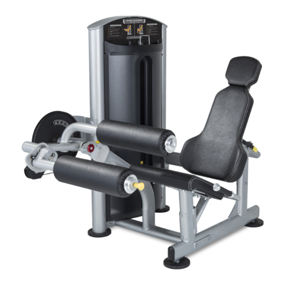
Obvious damage to external packaging / internal product. Please refuse the shipment and it will be returned to TRUE Fitness by the carrier. Contact the TRUE Fitness customer support team by calling 800.883.8783 or sales support team by calling 800.426.6570 Monday-Friday during normal business hours to notify us that the shipment has been refused. Once we have received the damaged shipment, a replacement shipment will be sent to you. - Page 47 LEG EXTENSION/ LEG CURL LEG EXTENSION/LEG CURL The TRUE FORCE Leg Extension/Leg Curl machine has revolutionized the ability to transition from extension to curl exercises, Users can now simply adjust positions with the pull of a knob, all while remaining seated on the machine. Like the rest of the FORCE Series, all adjustment for both exercises are and clearly labeled to provide users with extreme ease of use and allow transitions between exercises to be quick and smooth.
- Page 48 TRUE is Impacting Fitness. TRUE has a thirty-four year history making the world’s most premium cardio equipment. Now, we are taking that same manufacturing and design quality and bringing it to you in the new FORCE strength line. All of the features you have come to associate with TRUE are found in the FORCE line…quality, durability, craftsmanship and superior aesthetics.
-
Page 49: Chapter 6: Additional Information
NOTE: Buying after-market products from a 3rd party will by contacting TRUE directly at: result in voided warranty. TRUE Fitness, Service Department 865 Hoff Road, St. Louis, MO 63366 Frame: The frame is warranted for defects in material and 1.800.883.8783... - Page 50 CHAPTER 6: ADDITIONAL INFORMATION Commercial Limited Warranty Force Strength Line Save Time and Register Online! Activate Multiple Warranties at truefitness.com The above Limited Warranty is subject to and will be in accordance with the conditions set forth below: NOTE TO AUTHORIZED WARRANTY LABOR PROVIDERS: Warranty labor reimbursement or warranty parts rights may 1.
- Page 51 If you prefer to mail your warranty card, have the owner of the product complete the information below and return it to TRUE Fitness within 30 days from the date of equipment installation.
Need help?
Do you have a question about the SD1000 and is the answer not in the manual?
Questions and answers