
Subscribe to Our Youtube Channel
Related Manuals for True Fitness FORCE


Summary of Contents for True Fitness FORCE
- Page 1 *Assembly Guide & Warranty Card Included FUNCTIONAL TRAINER OWNER’S MANUAL Model # SM1000 Revision 102519...
- Page 2 FORCE STRENGTH OWNERS MANUAL IMPORTANT: All Products shown are prototype. Actual product delivered may vary. Product specifications, features & software are subject to change without notice. For the most up to date owner’s manual please visit www.truefitness.com. For documents in additional languages please visit www.truefitness.com/resources/document-library/ IMPORTANTE: Todos los productos mostrados son prototipos.
- Page 3 FORCE STRENGTH OWNERS MANUAL Frank Trulaske began TRUE Fitness over thirty-five year ago with the simple philosophy of delivering superior fitness products, service and support. Today, TRUE is the global leader in premium fitness equipment for the commercial and residential markets. Our goal is to be the leader in technology, innovation, performance, safety and style.
-
Page 4: Table Of Contents
FORCE STRENGTH OWNERS MANUAL TABLE OF CONTENTS: Chapter 1: Safety Instructions Chapter 5: Customer Service Safety Instructions Contacting Service Space Requirements Contacting Sales Working Dimensions Reporting Freight Claims or Parts Damage Warning Decals Chapter 6: Additional Information Proper Training Position... -
Page 5: Chapter 1: Safety Instructions
IMPORTANT SAFETY INSTRUCTIONS SAVE THESE SAFETY INSTRUCTIONS Force series strength equipment is intended for a commercial or institutional setting. This owner’s manual should be accessible to all personal trainers, staff members, and members. WARNING: All EXERCISERS MUST READ ALL INSTRUCTIONS BEFORE USING STRENGHT EQUIPMENT. - Page 6 CHAPTER 1: SAFETY INSTRUCTIONS CAUTION: • Health related injuries may result from incorrect or excessive use of exercise equipment. • Take care when getting on or off strength equipment. • If you do not understand how to use/operate a piece of equipment seek assistance from facility staff or trainer to demonstrate safe and proper use.
-
Page 7: Space Requirements
CHAPTER 1: SAFETY INSTRUCTIONS SPACE REQUIREMENTS: TRUE’s recommendation is to leave a 100” (2.54m) safety zone on the front and sides of the unit and a 40” safety zone behind. Additionally for Functional Trainers there should be enough room left for full extension of all cable in all directions. (See Fig 1) WORKING DIMENSIONS: Truefitness.com / 800.426.6570 / 636.272.7100... -
Page 8: Warning Decals
WARNING DECALS: WARNING: Replace warning labels that may be worn, damaged or missing. *To replace any worn or missing warning decals contact TRUE Fitness by one of the following: www.truefitness.com or contact customer service at 800-883-8783. Truefitness.com / 800.426.6570 / 636.272.7100... -
Page 9: Proper Training Position
CHAPTER 1: SAFETY INSTRUCTIONS PROPER TRAINING POSITION: Refer to the instructional placards (shown below) on the equipment for specific exercises, targeted muscle groups and proper training positions. Truefitness.com / 800.426.6570 / 636.272.7100... - Page 10 The assembly of this product requires at least two people to ensure that it is safely and properly assembled. • When ordering, use part number and description from the lists. Use only True Fitness replacement part when servicing. Failure to do so will void your warranty and could result in personal injury or damage your machine.
-
Page 11: Pre-Assembly Checklist
CHAPTER 2: ASSEMBLY GUIDE PRE-ASSEMBLY CHECKLIST: Box One Contents: Item No. Description QTY. Main Frame Foot Frame Support Frame Connecting Frame Double Pulley Bracket Pulley Bracket w/Shaft Left Column Right Column Guide Rod Chin Up Bar Accessory Rack Support Hook Plate Pulley Pulley Cover Cable... - Page 12 CHAPTER 2: ASSEMBLY GUIDE PRE-ASSEMBLY CHECKLIST: Box Two Contents: Item No. Description QTY. Rear Shroud Bracket Middle Shroud Bracket Front Shroud Bracket Front Shroud A Front Shroud B Rear Shroud Weight Plate Cartons: Weight Plates are packaged (4) per box. The shipment should contain (10) Boxes of weight plates for a total of 40 weight plates.
-
Page 13: Assembly Steps
CHAPTER 2: ASSEMBLY GUIDE UNIT ASSEMBLY STEPS: STEP 1 Frame Assembly: 1. Attach each Foot Frame to each Main Frame ITEM Description Flat Washer 11x20x2 as shown below. Socket Head Cap Screw M10x130 Nylon Lock Nuts M10 Main Frame Foot Frame Truefitness.com / 800.426.6570 / 636.272.7100... - Page 14 CHAPTER 2: ASSEMBLY GUIDE UNIT ASSEMBLY STEPS (continued): STEP 2 Lower Rear Shroud Brackets & Hook Plates: ITEM Description 1. Attach one Hook plate to each Main Frame. Flat Washers 9x22x2 Socket Head Cap Screw M8x25 2. Attach one Rear Shroud Bracket at the bottom Hexagon Socket Button Head Screw M8x20 of each Main Frame.
- Page 15 CHAPTER 2: ASSEMBLY GUIDE UNIT ASSEMBLY STEPS (continued): STEP 3 Upper Rear Shroud Brackets & Front Shroud Brackets: 1. Attach one Rear Shroud Bracket at the top of ITEM Description Flat Washers 9x22x2 each Main Frame as shown below. Button Head Cap Screw M8x20 2.
- Page 16 CHAPTER 2: ASSEMBLY GUIDE UNIT ASSEMBLY STEPS (continued): STEP 4 Support Frame & Connecting Frame: 1. Install the Support Frame & Connecting ITEM Description Flat Washers 11x20x2 Frame as shown below. Socket Head Cap Screw M10x25 Connecting Frame Support Frame Truefitness.com / 800.426.6570 / 636.272.7100...
- Page 17 CHAPTER 2: ASSEMBLY GUIDE UNIT ASSEMBLY STEPS (continued): STEP 5 Columns: ITEM Description 1. Install the Columns as shown below. Flat Washer 11x20x2 Socket Head Cap Screw M10x75 Socket head Cap Screw M8x85 Nylon Lock Nut M10 Bumper 20x10x16 Left Column Right Column Truefitness.com / 800.426.6570 / 636.272.7100...
- Page 18 CHAPTER 2: ASSEMBLY GUIDE UNIT ASSEMBLY STEPS (continued): STEP 6 Chin-Up Bar: ITEM Description 1. Install the Chin-Up Bar as shown below. Socket head Cap Screw M10x25 Flat Washer 11x20x2 Chin-Up Bar Truefitness.com / 800.426.6570 / 636.272.7100...
- Page 19 CHAPTER 2: ASSEMBLY GUIDE UNIT ASSEMBLY STEPS (continued): STEP 7 Cup Holder Assembly: 1. Install the Cup Holder Assembly as shown below. ITEM Description Flat Washer 6.6x12x1.6 Self-Tapping Screw ST4.2x13 Hexagon Socket Button Head Screw M6x20 Cross Recessed Countersunk Head Screw M6x10 Nylon Lock Nut M6 Accessory Rack Accessory Rack Support...
- Page 20 CHAPTER 2: ASSEMBLY GUIDE UNIT ASSEMBLY STEPS (continued): STEP 8 Double Pulley Brackets: 1. Install the Double Pulley Brackets as shown below. Description Flat Washer 9x22x2 Socket Head Cap Screw M8x100 Nylon Lock Nut M8 Double Pulley Bracket Truefitness.com / 800.426.6570 / 636.272.7100...
- Page 21 CHAPTER 2: ASSEMBLY GUIDE UNIT ASSEMBLY STEPS (continued): STEP 9 Weight Stack Assembly: 1. Assemble and install the Weight Stacks as ITEM Description Rubber Weight Bumper shown below. Flat Washer 9x22x2 Socket Head Cap Screw M8x50 Nylon Lock Nut M8 Middle Shroud Bracket Guide Rods Pulley Bracket...
- Page 22 CHAPTER 2: ASSEMBLY GUIDE UNIT ASSEMBLY STEPS (continued): STEP 10 Cable Routing: 1. Route each Cable as shown below. 2. Verify that no more than 1 inch (25.4mm) of CAUTION the threaded portion of the cable bolt is visible between the Cable Nut and the cap of the Cable A minimum of 1/2 inch (12.7mm) of the threaded Bolt.
- Page 23 CHAPTER 2: ASSEMBLY GUIDE UNIT ASSEMBLY STEPS (continued): STEP 11 Pulley Covers: ITEM Description 1. Install the Pulley Covers on each side of the Socket Head Cap Screw M10x55 unit as shown below. Nylon Lock Nut M10 Pulley Cover Pulley Cover Truefitness.com / 800.426.6570 / 636.272.7100...
- Page 24 CHAPTER 2: ASSEMBLY GUIDE UNIT ASSEMBLY STEPS (continued): STEP 12 Shrouds: ITEM Description 1. Install the Shrouds as shown. Flat Washer 9x22x2 Hexagon Socket Button Head Screw M8x20 Truefitness.com / 800.426.6570 / 636.272.7100...
- Page 25 CHAPTER 2: ASSEMBLY GUIDE UNIT ASSEMBLY STEPS (continued): STEP 13 Handle Straps & Other Accessories: ITEM Description 1. Attach the Handle Straps using snap links. Snap Link 2. Hang the additional accessories on the mounting Hooks and Hook Plates as shown. Handle Strap Truefitness.com / 800.426.6570 / 636.272.7100...
-
Page 26: Product Overview
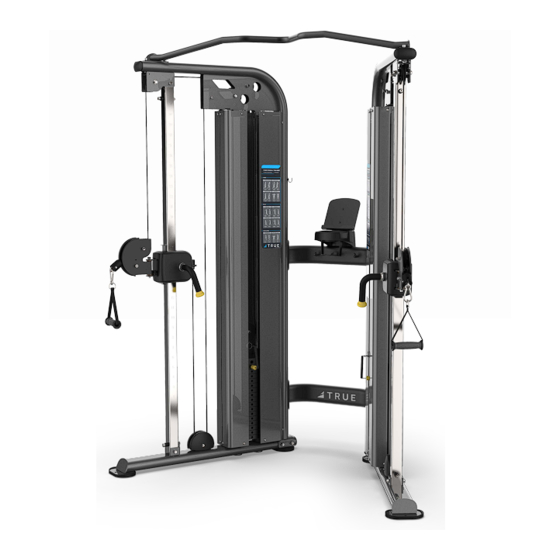
CHAPTER 3: PRODUCT OVERVIEW FUNCTIONAL TRAINER OVERVI Workout Handle Adjustment Lever Workout Handle Adjustment Lever Weight Stack Adjustment Pins Truefitness.com / 800.426.6570 / 636.272.7100... -
Page 27: Chapter 4: Care & Maintenance
The following items are critical to the safety of users and maintenance staff as well as to ensure the optimum performance of the machines. These inspections should be performed each day before the equipment is subject to use. TRUE Fitness is not responsible for performing or scheduling regular maintenance or inspections. -
Page 28: Other Scheduled Preventive Maintenance
CAUTION Do not use any acidic cleaners. Doing so will weaken the paint or powder coatings and may void the TRUE Fitness Warranty. Never pour or spray liquids on any part of the equipment. Allow the equipment to dry completely before using. -
Page 29: Cable Inspection & Maintenance
If any of these conditions are apparent, the machine should immediately be taken out of service and repaired. Be sure to use only cables supplied by TRUE Fitness. DO NOT use cables that have fittings attached with hand- crimp tools. - Page 30 CHAPTER 4: CARE & MAINTENANCE CABLE INSPECTION & MAINTENANCE (continued): Cable Tension: Ensure that the cables are adjusted to remove any slack using the threaded end fittings. These are normally located at the weight stack connection. Depending upon the machine, there may be multiple threaded fitting on multiple cables. You can determine if there is too much slack by performing the exercise.
-
Page 31: Chapter 5: Customer Service
CONTACTING SERVICE: TRUE Fitness recommends that you gather the serial number, model number, and a brief description of the reason for the request. After information has been gathered you may choose to contact your selling dealer or local service company to set an appointment. -
Page 32: Reporting Freight Claims Or Parts Damage
Obvious damage to external packaging / internal product. Please refuse the shipment and it will be returned to TRUE Fitness by the carrier. Contact the TRUE Fitness customer support team by calling 800.883.8783 or sales support team by calling 800.426.6570 Monday-Friday during normal business hours to notify us that the shipment has been refused. Once we have received the damaged shipment, a replacement shipment will be sent to you. -
Page 33: Chapter 6: Additional Information
TRUE) for one year from date of purchase. * This limited warranty on structural frame does not include paint or coatings. Parts: The Force Strength Line’s mechanical parts and are warranted for defects in material and workmanship for five years with one year labor warranty. Cables and belts are warranted for defects in material and workmanship for one year with one year labor warranty.This limited warranty does... - Page 34 Warranty to be valid. 2. This Limited Warranty applies to the product only while the The Force Strength Line comes with one serial number on the Product remains in the possession of the original purchaser base of the machine. Please write down your serial number and is not transferable.
-
Page 35: Warranty Registration
If you prefer to mail your warranty card, have the owner of the product complete the information below and return it to TRUE Fitness within 30 days from the date of equipment installation.
Need help?
Do you have a question about the FORCE and is the answer not in the manual?
Questions and answers