Oriental motor BLH Series Operating Manual
Brushless motor and driver package
Hide thumbs
Also See for BLH Series:
- User manual (148 pages) ,
- Operating manual (68 pages) ,
- Operating manual (24 pages)
Table of Contents
Advertisement
Brushless Motor and Driver Package
BLH Series
OPERATING MANUAL
Thank you for purchasing an Oriental Motor product.
This operating manual describes product handling procedures and safety precautions.
• Please read it thoroughly to ensure safe operation.
• Always keep the manual where it is readily available.
Table of contents
1 Introduction .................................. 2
2 Safety precautions ....................... 4
3 Precautions for use ...................... 7
4 Preparation................................... 8
4.1
Checking the product .................. 8
4.2
Combination tables ..................... 9
4.3
Names and function of parts ..... 11
5 Installation .................................. 12
5.1
Installation location ................... 12
5.2
gearhead................................... 13
5.3
hollow shaft flat gearhead ......... 15
5.4
5.5
5.6
type ........................................... 19
5.7
gearhead................................... 22
5.8
Driver installation ...................... 24
5.9
with EMC Directive ................... 25
6 Connection..................................29
6.1
Motor and driver connection..... 29
6.2
Connecting the power supply ... 29
6.3
output signal ............................. 30
6.4
connection ................................ 32
7 Operation ....................................33
7.1
output signals ........................... 33
7.2
output shaft............................... 40
7.3
Setting the running speed ........ 41
7.4
deceleration time ...................... 44
7.5
Parallel operation ..................... 45
8 Inspection....................................47
actions ........................................48
10 Appendix .....................................50
10.2 Recommended peripherals ...... 51
HM-5130
Advertisement
Table of Contents

Related Manuals for Oriental motor BLH Series


Summary of Contents for Oriental motor BLH Series
-
Page 1: Table Of Contents
Brushless Motor and Driver Package BLH Series OPERATING MANUAL Thank you for purchasing an Oriental Motor product. This operating manual describes product handling procedures and safety precautions. • Please read it thoroughly to ensure safe operation. • Always keep the manual where it is readily available. -
Page 2: Introduction
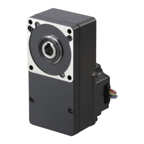
Overview of the product The BLH series is a brushless motor unit that adopts a slim, high-torque brushless motor and an open-case high-precision compact driver of 24 VDC input type. The product is available in three types;... - Page 3 1 Introduction • For Low Voltage Directive • Since this product is based on 24 VDC power supply input, it is outside the application scope of Low Voltage Directives. • When applying the equipment incorporating this product to the Low Voltage Directive, connect the driver power supply input to the DC power supply where the primary and secondary sides are provided with reinforced insulation.
-
Page 4: Safety Precautions
2 Safety precautions 2 Safety precautions Only qualified personnel should work with the product. Use the product correctly after thoroughly reading the section “Safety precautions”. The precautions described below are intended to prevent danger or injury to the user and other personnel through safe, correct use of the product. Use the product only after carefully reading and fully understanding these instructions. - Page 5 2 Safety precautions Operation • Turn off the driver power supply in the event of a power failure, or the motor may suddenly start when the power is restored and may cause injury or damage to equipment. • Do not use it in a vertical applications. When the driver protection function is triggered, the motor will stop operating.
- Page 6 2 Safety precautions • Before moving the motor directly with the hands (as in the case of manual positioning), confirm that the driver operation input is “OFF” to prevent injury. • Do not perform the motor’s starting and stopping operations by turning the power supply on and off.
-
Page 7: Precautions For Use
BLH series. • Do not perform gravitational load operation With the BLH series, any operation in which the motor output shaft is turned from the load side (gravitational load operation) will disable the motor speed control. In addition, a gravitational load operation will cause the driver’s primary inverter voltage to exceed the allowable value, thereby triggering a protection function and causing the motor to stop spontaneously. -
Page 8: Preparation
4 Preparation 4 Preparation The following describes the items to be confirmed, names and functions of individual components. 4.1 Checking the product Open the package and make sure that the following items are supplied. The supplied items vary depending on the product. If there is any shortage or damage, contact the sales office where you bought the product. -
Page 9: Combination Tables
4 Preparation 4.2 Combination tables Geared type The motor and gearhead are integrated. The combination of motor and gearhead cannot be changed. Components model Unit model Motor model Driver model BLH015K- BLHM015K- BLHD15K in the model names indicates a number representing the gear ratio (5, 10, 15, 20, 30, 50 or 100). - Page 10 4 Preparation Round shaft type Components model ∗ Unit model ∗ Motor model Driver model BLH015K-A BLHM015K-A BLHD15K BLH230KC-A BLHM230KC-A BLHD30K BLH450KC-A BLHM450KC-A BLHD50K BLH5100KC-A BLHM5100KC-A BLHD100K ∗ For the lead wire type, “KC” of the unit model and motor model are replaced by “K” (except for BLH015 type).
-
Page 11: Names And Function Of Parts
4 Preparation 4.3 Names and function of parts The following describes the names and functions of individual components of the driver. Driver model: BLHD15K, BLHD30K, BLHD50K Mounting holes (2 positions) Heat sink Power supply connector (CN1) Installation notch Connect the power supply cable. (2 positions) ➙... -
Page 12: Installation
5 Installation 5 Installation This chapter explains the installation location and installation methods of the motor and driver, as well as how to install a load. Read the applicable sections carefully to install each item correctly. Geared type P.13, 19 Combination type parallel shaft gearhead Combination type hollow shaft flat gearhead P.15, 22... -
Page 13: Installing The Geared Type, Combination Type Parallel Shaft Gearhead
5 Installation 5.2 Installing the geared type, combination type parallel shaft gearhead Open mounting holes in the mounting plate. [Unit: mm (in.)] 4×ØD Unit ØA ØB ØD model 43.8 BLH015 (1.72) (0.63) (0.31) (0.177) BLH230 (2.76) (0.94) (0.39) (0.177) BLH450 (3.70) (1.34) (0.51) - Page 14 5 Installation • Geared type To install the motor, use the four installation holes and mount the motor with four bolts (not provided) so that there is no gap with the mounting plate. Effective depth of bolt: 8 mm (0.31 in.) Unit model Nominal thread size Tightening torque BLH015...
-
Page 15: Installing The Combination Type Hollow Shaft Flat Gearhead
5 Installation Change the cable position to a desired Unit Nominal Tightening 90° direction. model thread size torque BLH230 0.4 N·m M2.6 BLH450 (3.5 lb-in) 0.6 N·m BLH5100 (5.3 lb-in) Pilot Note • Do not forcibly assemble the motor and gearhead. Also, do not let metal objects or other foreign matters enter the gearhead. - Page 16 5 Installation • Using the front side as the mounting surface When the gearhead is installed by using its front side as the mounting surface, use the boss of the output shaft to align the center. Safety cover Safety cover Hexagonal socket head screws mounting screws (M3) ·...
- Page 17 5 Installation Maximum applicable plate thickness Maximum applicable Unit model plate thickness BLH230 5 mm (0.20 in.) BLH450 8 mm (0.31 in.) BLH5100 12 mm (0.47 in.) ∗ The figures in the table apply when the supplied hexagonal socket head screw is used. Changing the motor cable’s routing direction The gearhead can be removed and the motor cable position changed to one of three 90°...
-
Page 18: Installing The Round Shaft Type
5 Installation Do not forcibly assemble the motor and gearhead. Also, do not let metal Note • objects or other foreign matters enter the gearhead. The pinion or gear of the motor output shaft may be damaged, resulting in noise or shorter service life. -
Page 19: Installing The Pinion Shaft Type
5 Installation 5.5 Installing the pinion shaft type A pinion shaft motor is used with a parallel shaft gearhead or hollow shaft flat gearhead assembled to it. Installing a parallel shaft gearhead: P.13, 19 Installing a hollow shaft flat gearhead: P.15, 22 5.6 Installing a load on the geared type, combination type parallel shaft gearhead and round shaft type When installing a load on the motor (gearhead), align the center of the motor output... - Page 20 5 Installation How to install a load • Using a coupling Align the centerline of the motor (gearhead) output shaft with the centerline of the load shaft. • Using a belt Adjust the motor (gearhead) output shaft to lie parallel with the load shaft and form right angles between the output shaft/load shaft and the line connecting the centers of both pulleys.
- Page 21 5 Installation Permissible overhung load and permissible thrust load Make sure the overhung load and thrust load received by the motor (gearhead) output shaft will not exceed the allowable values shown in the table below. If the overhung load or thrust load exceeds the specified allowable value, Note repeated load applications may cause the bearing or output shaft of the motor (gearhead) to undergo a fatigue failure.
-
Page 22: Installing A Load On The Combination Type Hollow Shaft Flat Gearhead
5 Installation 5.7 Installing a load on the combination type hollow shaft flat gearhead If the motor receives a significant impact upon instantaneous stop or is subject to a large overhung load, affix the stepped load shaft. Note Apply grease (molybdenum disulfide grease, etc.) on the surface of the load shaft and inner walls of the hollow output shaft to prevent seizure. - Page 23 5 Installation Recommended load shaft installation dimensions [Unit: mm (in.)] Inner diameter of Recommended tolerance Nominal diameter of Unit model hollow shaft of load shaft retaining ring Ø12 +0.027 Ø12 BLH230 -0.018 Ø12 (Ø0.47) (Ø0.4724 +0.0011 (Ø0.4724 -0.0007 Ø15 +0.027 Ø15 BLH450 -0.018...
-
Page 24: Driver Installation
5 Installation 5.8 Driver installation Direction of installation The driver is designed on the basis of heat radiation by air convection and heat conduction to the housing. When installing the driver in the housing, use four installation holes on the driver and install it in the vertical or horizontal direction. -
Page 25: Installing And Wiring In Compliance With Emc Directive
EN 61000-6-2 Installing and wiring in compliance with EMC Directive Effective measures must be taken against the EMI that the BLH series may give to adjacent control-system equipment, as well as the EMS of the BLH series itself, in order to prevent a serious functional impediment in the machinery. - Page 26 5 Installation Connecting mains filter for power supply line Install a mains filter in the AC input line to the DC power supply in order to prevent the noise generated within the driver or control system from propagating outside via the DC power supply.
- Page 27 5 Installation How to ground The wire used to ground the motor and driver must be as thick and short to the grounding point as possible so that no potential difference is generated. Choose a large, thick and uniformly conductive surface for the grounding point. •...
- Page 28 5 Installation Example of motor and driver installation and wiring Motor Driver Ferrite core ∗ Motor cable Cable clamp DC power Mains supply filter Cable Signal cable clamp [Shielded cable : 2 m (6.6 ft.)] Power supply cable (Shielded cable) (Grounded panel) ∗...
-
Page 29: Connection
6 Connection 6 Connection The following shows the method of connecting the motor and driver, power supply, external potentiometer, earth connection method, an example of connection and I/O signals. 6.1 Motor and driver connection Insert the motor cable connector into the motor connector of the driver. Unit model Motor connector BLH015, BLH230, BLH450... -
Page 30: Connection Of Input Signal And Output Signal
6 Connection 6.3 Connection of input signal and output signal Connection with driver Insert the connector of the I/O signals cable into the connector of the I/O signals cable (CN2) of the driver. The colors in the figure indicate the colors of supplied cables. - Page 31 6 Connection • BLH5100 +24 V Power supply input Black 24 VDC±10% START/STOP OFF ON Black input RUN/BRAKE OFF ON White input CW/CCW OFF ON input Gray INT.VR/EXT OFF ON input Light Blue ALARM-RESET OFF ON External Purple input potentiometer ∗ 20 kΩ...
-
Page 32: Driver I/O Circuit And Example Connection
6 Connection 6.4 Driver I/O circuit and example connection Input signal The driver’s signal input is a C-MOS input. The signal status indicates “0 to 0.5 V (L level) when ON,” or “4 to 5 V (H level) when OFF.” •... -
Page 33: Operation
7 Operation 7 Operation 7.1 Input signals and output signals Do not perform the motor’s starting and stopping operations by Caution turning the power supply on and off. Perform them by inputting START/STOP and RUN/BRAKE. This may cause injury or damage to the equipment. - Page 34 7 Operation RUN/BRAKE input RUN is selected when the input is ON, and motor starts running. BRAKE is selected when the input is OFF, and motor stops instantaneously. ∗ 10 ms or more START/STOP input STOP START RUN/BRAKE input BRAKE ∗...
- Page 35 7 Operation INT.VR/EXT input INT.VR is selected when the input is ON, and the setting speed of internal potentiometer is enabled. EXT is selected when the input is OFF, and the setting speed of external potentiometer or external DC voltage is enabled. Switching this signal allows combined use of the external potentiometer or external DC voltage or two-speed switching operation.
- Page 36 7 Operation ALARM-RESET input Use the ALARM-RESET input if you need to move the motor to a specified position or the mechanical home position after the motor has stopped in the middle of operation due to an actuation of the driver’s protective function (ALARM output: OFF).
- Page 37 7 Operation SPEED output Pulse signals (pulse width: 0.3 ms) of 30 pulses per revolution of the motor output shaft are output in synchronism with the motor drive. Motor speed can be calculated by measuring the SPEED output frequency. ∗ SPEED output frequency [Hz] ×...
- Page 38 7 Operation Number of Protection function ALARM LED Assumed causes flashes • When a load in excess of the rated torque was applied to the motor for about 5 s or more. Overload 2 times protection function • When the motor running/instantaneous stop and drive direction switching was repeated in a short time.
- Page 39 7 Operation Timing chart Two-step speed selection, Run, Direction of rotation deceleration stop Instantaneous stop selection ∗3 High speed ∗3 ∗3 ∗3 ∗2 (Clockwise direction) speed ∗3 ∗3 Motor operating pattern (Counterclockwise ∗2 direction) ∗3 START/ START START STOP input ∗1 ∗1 CCW input...
-
Page 40: Rotating Direction Of The Motor Output Shaft
7 Operation 7.2 Rotating direction of the motor output shaft The rotating direction of the motor output shaft is defined as clockwise (CW) or counterclockwise (CCW) as viewed from the motor output shaft. However, the rotating direction of the motor output shaft may vary from that of the gearhead output shaft depending on the gear ratio of the gearhead. -
Page 41: Setting The Running Speed
7 Operation 7.3 Setting the running speed Set the operating speed of the motor using the internal speed potentiometer, external speed potentiometer or external DC voltage. The motor speed range is from 100 to 3000 r/min for the case of the motor alone. Two running speeds can be set by combining the internal potentiometer and external potentiometer, or the internal potentiometer and external DC voltage. - Page 42 7 Operation Setting by external potentiometer This potentiometer is used when the speed is set away from the driver or when two-step speed switching is performed in combination with the internal potentiometer. Use the accessory PAVR-20KZ as the external potentiometer. Clockwise rotation will increase the set speed.
- Page 43 7 Operation Setting by external DC voltage External DC voltage is used when the speed is set by D/A output from an external control device such as a programmable controller, or when the speed is switched over two levels during operation in combination with the internal speed potentiometer.
-
Page 44: Setting The Acceleration Time And Deceleration Time
7 Operation 7.4 Setting the acceleration time and deceleration time Set the acceleration time and deceleration time using the acceleration/deceleration time potentiometer (page 11). The acceleration time and deceleration time are always identical. Adjust the potentiometer using an insulated screwdriver. Turning the potentiometer clockwise increases the time. -
Page 45: Parallel Operation
7 Operation 7.5 Parallel operation If two or more motors are to be operated at the same speed, they can be controlled from the DC power supply or external potentiometer. Use external DC power supply • Use a DC power supply whose current capacity is at least the value calculated by the formula below: Current capacity when N drivers are connected: I = 1 ×... - Page 46 7 Operation Use an external potentiometer Use common lines for the power supply and speed control and set the speed using VRx, as shown below. • Obtain the resistance for the external speed potentiometer as follows: Resistance when N drivers are connected: VRx = 20/N (kΩ), N/4 (W) Example: If two drivers are connected, the current capacity should be 10 kΩ, 1/2 W.
-
Page 47: Inspection
8 Inspection 8 Inspection It is recommended to check the following four items after motor operation. If any failure is found, stop the operation, and please contact your local sales office. Inspection items • Check if abnormal noise is produced from the motor bearing section (ball bearing). -
Page 48: Troubleshooting And Remedial Actions
9 Troubleshooting and remedial actions 9 Troubleshooting and remedial actions During motor running, the motor and driver may not operate correctly due to speed setting error or connection error. If normal motor operation cannot be ensured, see the following description and take appropriate countermeasures. If normal operation cannot be ensured even after that, please contact your local sales office. - Page 49 9 Troubleshooting and remedial actions Phenomenon Estimated cause Measure The motors driven in the CW direction when the CW/CCW input Incorrect CW/CCW input or is set to the ON. CCW direction faulty connection. when the CW/CCW input is set to the OFF.
-
Page 50: Appendix
10 Appendix 10 Appendix 10.1 Accessories (sold separately) Extension cable Use this cable to extend the wiring distance between the motor and driver. Model Length Applicable product CC02BLH BLH015, BLH230, BLH450 1.5 m (4.9 ft.) CC02AXH2 BLH5100 External potentiometer Model: PAVR-20KZ •... -
Page 51: Recommended Peripherals
Note The digital speed indicator SDM496 is not certified under the safety standards. If the SDM496 is combined with the BLH series, conformance of the BLH series with the safety standards is not guaranteed. 10.2 Recommended peripherals... - Page 52 If a new copy is required to replace an original manual that has been damaged or lost, please contact your nearest Oriental Motor branch or sales office. • Oriental Motor shall not be liable whatsoever for any problems relating to industrial property rights arising from use of any information, circuit, equipment or device provided or referenced in this manual.
Need help?
Do you have a question about the BLH Series and is the answer not in the manual?
Questions and answers