Oriental motor BLH Series Operating Manual
Brushless motor, rs-485 communication type
Hide thumbs
Also See for BLH Series:
- User manual (148 pages) ,
- Operating manual (68 pages) ,
- Operating manual (7 pages)
Table of Contents
Advertisement
Brushless Motor
BLH Series
RS-485 communication type
OPERATING MANUAL
Thank you for purchasing an Oriental Motor product.
This Operating Manual describes product handling procedures and safety precautions.
• Please read it thoroughly to ensure safe operation.
• Always keep the manual where it is readily available.
Table of contents
1 Introduction ..........................................................2
2 Safety precautions ..............................................3
3 Precautions for use .............................................4
4 Preparation ............................................................5
5 Installation .............................................................7
6 Connection ............................................................8
6.1 Connecting the motor and driver (CN3) ............ 8
6.2 Connecting the power supply (CN1) ................... 8
6.3 Grounding ..................................................................... 9
6.4 Connecting the I/O signals (CN2) ......................... 9
6.5 Driver I/O circuit ........................................................10
devices ..........................................................................11
6.7 Connecting the USB cable (CN4) ........................12
cable (CN5, CN6) .......................................................12
6.9 Connection diagram ...............................................13
6.10 Noise elimination measures .................................14
6.11 Conformity to the EMC Directive ........................14
7 Guidance ............................................................. 16
8 Maintenance and inspection ....................... 19
9 Specifications ..................................................... 20
10 Regulations and standards ........................... 22
HP-5111
Advertisement
Table of Contents

Related Manuals for Oriental motor BLH Series


Summary of Contents for Oriental motor BLH Series
-
Page 1: Table Of Contents
BLH Series RS-485 communication type OPERATING MANUAL Thank you for purchasing an Oriental Motor product. This Operating Manual describes product handling procedures and safety precautions. • Please read it thoroughly to ensure safe operation. • Always keep the manual where it is readily available. -
Page 2: Introduction
Do not use for any other purpose. For the power supply, use a DC power supply with reinforced insulation on its primary and secondary sides. Oriental Motor Co., Ltd. is not responsible for any damage caused through failure to observe this warning. -
Page 3: Safety Precautions
Safety precautions 2 Safety precautions The precautions described below are intended to ensure the safe and correct use of the product, and to prevent the user and other personnel from exposure to the risk of injury. Use the product only after carefully reading and fully understanding these instructions. -
Page 4: Precautions For Use
Precautions for use 3 Precautions for use This chapter covers limitations and requirements the user should consider when using the product. Be sure to match the output power of the driver with that of the motor when using. z Notes for continuous regeneration operation When regeneration operation is continuously performed, check the following conditions are satisfied before use. -
Page 5: Preparation
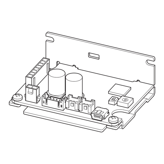
□ Driver ..........1 unit □ OPERATING MANUAL ....1 copy 4.2 How to identify the product model BLH2D 30 - K R ① Driver type BLH2D: BLH Series driver ② Output power 15: 15 W 30: 30 W 50: 50 W ① ②... - Page 6 Preparation 4.5 Names and functions of parts This section explains the name and function for each part of the driver. Termination resistor switch (TERM.) Motor connector (CN3) Address number setting switch (ID) TERM. C-DAT C-ERR PWR/ALM Power supply connector (CN1) USB connector (CN4) LED (PWR/ALM) RS-485 communication connector (CN5)
-
Page 7: Installation
Installation 5 Installation 5.1 Installation location The driver is designed and manufactured to be incorporated in equipment. Install it in a well-ventilated location that provides easy access for inspection. The location must also satisfy the following conditions: • Inside an enclosure that is installed indoors (provide vent holes) •... -
Page 8: Connection
Connection 6 Connection This chapter explains how to connect the driver with the motor, power supply, and I/O signals. 6.1 Connecting the motor and driver (CN3) Insert the motor cable connector into the motor connector (CN3) on the driver. When extending the motor cable, use a connection cable (sold separately). The maximum extension distance including the cable length of the motor itself should be 2 m (6.6 ft.). -
Page 9: Grounding
Connection 6.3 Grounding The wire used to ground the motor and driver must be as thick and short to the grounding point as possible so that no potential difference is generated. Choose a large, thick and uniformly conductive surface for the grounding point. z Grounding the motor z Grounding the driver Connect the grounding wire along with a set... -
Page 10: Driver I/O Circuit
Connection 6.5 Driver I/O circuit „ Input signals circuit „ Input signals of the driver are C-MOS inputs. Driver internal circuit The signal state represents "ON: 0 to 0.5 V (L level)" and +5 V "OFF: 4 to 5 V (H level)". 10 kΩ... -
Page 11: Connecting External Analog Setting Devices
Connection 6.6 Connecting external analog setting devices Using an external potentiometer (sold separately), external DC voltage, or PWM signal input, the rotation speed or the torque limiting value can be set. „ Using an external potentiometer „ External potentiometer Connect to the pin Nos. 4 to 6 of the CN2. PAVR2-20K (sold separately) When the PAVR2-20K is used, use the ferrule (rod terminal). -
Page 12: Connecting The Usb Cable (Cn4)
Connection 6.7 Connecting the USB cable (CN4) When the MEXE02 is used, connect the USB Specifications of USB cable cable to the USB connector. Specification USB2.0 (full speed) Cable Length: 3 m (9.8 ft.) or less Shape: A to mini B •... -
Page 13: Connection Diagram
6.9 Connection diagram A connection example of I/O signals with a programmable controller are as shown below. The I/O signals circuit of the BLH Series RS-485 communication type are configured with current SINK logic. (Current SOURCE logic is not supported.) -
Page 14: Noise Elimination Measures
„ About power supply „ The BLH Series is a product of DC power supply input. Use a DC power supply (such as a switching power supply) that optimally conforms to the EMC Directive. „ Connecting the motor cable „... - Page 15 Connection „ Notes about installation and wiring „ • Connect the motor, driver and other peripheral control equipment directly to the grounding point so as to prevent a potential difference from developing between grounds. • When relays or electromagnetic switches are used together with the system, use noise filters and CR circuits to suppress surges generated by them.
-
Page 16: Guidance
Guidance 7 Guidance If you are new to this product, read this chapter to understand the operating methods along with the operation flow. This is an example how to set operation data and parameters to the driver and operate the motor using a host controller. Refer to the USER MANUAL for details. - Page 17 Guidance STEP2 Setting switches Set the termination resistor and the address number with the switches. Turn off the driver power before setting the switches. If the switches are set while the power is still on, the new switch Note settings will not be enabled. Termination resistor switch (TERM.) TERM.
- Page 18 Guidance STEP4 Turning on the power supply again The address number setting switch and the communication parameters of the driver will be updated after turning on the power supply again. STEP5 Operating the motor Send a message to operate the motor. As an example, this section explains how to perform the following operation. Rotation speed 2500 r/min Time...
-
Page 19: Maintenance And Inspection
It is recommended that periodic inspections are conducted for the items listed below after each operation of the motor. If an abnormal condition is noted, discontinue any use and contact your nearest Oriental Motor sales office. • Do not conduct the insulation resistance measurement or the dielectric strength test with the motor and driver Note connected. -
Page 20: Specifications
2500 r/min Speed control range ) 100 to 3000 r/min Digital setting Check on the Oriental Motor Website for the product specifications. 9.2 General specifications Ambient temperature Driver: 0 to +50 °C [+32 to +122 °F] (non-freezing) Ambient humidity 85% or less (non-condensing) Altitude Up to 1000 m (3300 ft.) above sea level... - Page 21 Specifications 9.4 Dimensions Mass: 46 g (1.62 oz.) [Unit: mm (in.)] 72 (2.83) max. 4 (0.157) (2.480 [50 (1.97)] ±0.2 ±0.008 2× 3.5 ( 0.138) Thru (2.520 3.5 (0.138) ±0.2 ±0.008 Installation of motor cable...
-
Page 22: Regulations And Standards
Regulations and standards 10 Regulations and standards 10.1 UL Standards, CSA Standards This product is recognized by UL under the UL and CSA Standards. Applicable Standards Certification body/Standards File No. UL 62368-1 UL/E208200 CSA C22.2 No.62368-1 10.2 EU Directives „ CE Marking „... - Page 23 Regulations and standards...
- Page 24 • Unauthorized reproduction or copying of all or part of this manual is prohibited. If a new copy is required to replace an original manual that has been damaged or lost, please contact your nearest Oriental Motor branch or sales office.
Need help?
Do you have a question about the BLH Series and is the answer not in the manual?
Questions and answers